
Single-Stub Matching
Interactive Audio Lesson
Listen to a student-teacher conversation explaining the topic in a relatable way.
Introduction to Single-Stub Matching
🔒 Unlock Audio Lesson
Sign up and enroll to listen to this audio lesson

Today, we are going to discuss single-stub matching. Does anyone know what a matching network is?

Is it used to connect different impedances together?
Exactly! A matching network helps in connecting different impedances to maximize power transfer. Now, single-stub matching specifically uses a stub to cancel out reactive components from the load. Who can tell me what a stub is?

Isn't it a section of transmission line used for matching?
Correct! We can either short or open-circuit the stub. Let's explore how changing the stub length affects the reactance.
Designing a Single-Stub Matching Network
🔒 Unlock Audio Lesson
Sign up and enroll to listen to this audio lesson

To design a single-stub matching network, we need to calculate the length of the stub. Can anyone think of how we might do that?

We might use the formulas related to impedance transformation?
Great suggestion! We use the relationship between the stub length and the load reactance to find that perfect match. Remember, our goal is to cancel the reactive part of the load impedance. What methods do we have to achieve this?

We can plot it on the Smith Chart, can’t we?
Yes! The Smith Chart is a powerful tool for these calculations. It helps us visualize where our load lies and how to adjust for reactance cancellation.
Application of Single-Stub Matching in RF Design
🔒 Unlock Audio Lesson
Sign up and enroll to listen to this audio lesson
Now that we know about single-stub matching, can anyone share where this might be used in real-world applications?
In RF circuits!
Exactly! RF circuits often encounter mismatched impedances, and using single-stub matching allows for efficient power transfer, especially in antennas and amplifiers. Why do you think minimizing reflections is crucial?
Because reflections can lead to signal loss and interference!
Correct! Reducing reflections enhances performance. Always remember, the main goal is to achieve a perfect impedance match.
Introduction & Overview
Read summaries of the section's main ideas at different levels of detail.
Quick Overview
Standard
Single-stub matching involves using a shunt stub to provide a matched impedance to a load. By adjusting the length of the stub, engineers can effectively cancel out the unwanted reactive components of the load impedance, leading to improved performance in RF applications.
Detailed
Single-Stub Matching
Overview
Single-stub matching is a crucial technique used in transmission line design to achieve impedance matching. It involves adding a stub to the transmission line, which can either be open-circuited or short-circuited. The primary goal is to adjust the stub's length in such a manner that it cancels the reactance present at the load, resulting in a matched condition that minimizes reflection and maximizes power transfer.
Key Points
- Stub Configuration: The stub is connected in a shunt configuration, making it possible to actively manipulate the load impedance.
- Reactance Cancellation: By changing the length of the stub, you can modify its reactance, effectively countering the reactive component of the load impedance.
- Design Procedure: The design typically involves using impedance transformation techniques and identifying the appropriate stub length to achieve the desired outcome.
Single-stub matching is often employed in RF and microwave circuits where precise impedance control is required to enhance performance, ensuring that devices operate efficiently without undesired signal reflections.
Youtube Videos


Audio Book
Dive deep into the subject with an immersive audiobook experience.
Overview of Single-Stub Matching
Chapter 1 of 2
🔒 Unlock Audio Chapter
Sign up and enroll to access the full audio experience
Chapter Content
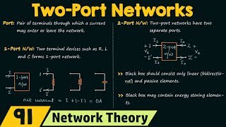
Single-Stub Matching
- Shunt Stub:
Source ──λ/4──┬── Load
│
Stub (Open/Short)
Detailed Explanation
Single-stub matching is a technique used to match the impedance of a load to a transmission line. The basic configuration involves a transmission line segment, typically a quarter wavelength long (λ/4), connected to a shunt stub. The stub can be either an open or short circuit, which helps to adjust the impedance seen by the transmission line to achieve a better match. The goal is to minimize reflections that would otherwise occur due to the mismatch between the load and the transmission line.
Examples & Analogies
Consider a water hose connecting to a sprinkler (the load). If the diameter of the hose does not match the opening of the sprinkler, water doesn't flow well, leading to wasted pressure. By adding a flexible connector (the stub), you can better match the sizes and ensure effective flow, similar to how the stub helps in achieving impedance matching.
Design Considerations for the Stub
Chapter 2 of 2
🔒 Unlock Audio Chapter
Sign up and enroll to access the full audio experience
Chapter Content
- Design: Adjust stub length to cancel reactance.
Detailed Explanation
In single-stub matching, the length of the stub is a critical parameter. It needs to be adjusted accurately to cancel out any reactive components of the impedance presented by the load. This can involve a bit of trial and error or calculated design based on the known values of the source and load impedances. The idea is that by introducing the stub, the overall impedance at the junction can be transformed to match the desired value, thereby minimizing reflections along the transmission line.
Examples & Analogies
Imagine tuning a guitar: you need to adjust the tension of each string to get the correct pitch. Each string's tension corresponds to its length and mass, similar to how adjusting the stub’s length affects the overall impedance. Just like tuning makes the guitar sound harmonious, adjusting the stub ensures that signal transmission is optimized.
Key Concepts
-
Single-Stub Matching: A technique for achieving impedance matching using a shunt stub.
-
Reactance Cancellation: Adjusting stub length to negate the reactive component of the load.
-
Impedance Transformation: Using techniques like the Smith Chart for design calculations.
Examples & Applications
If a load has a reactive component of +j50Ω, a single-stub can be tuned to present a compensating reactance of -j50Ω.
In an RF amplifier circuit, a single-stub matcher can allow for maximum power transfer from the amplifier to the antenna.
Memory Aids
Interactive tools to help you remember key concepts
Rhymes
When you need a match without a scratch, use a stub that's just the catch!
Stories
Imagine an engineer trying to connect a mismatched load to an antenna. They carefully adjust a stub, finding the right length, and suddenly, all reflections disappear — they’ve made a perfect match!
Memory Tools
S.T.U.B. - Stick To Using a 'Balanced' approach in matching networks!
Flash Cards
Glossary
- Impedance Matching
The process of making the input impedance of a system equal to the output impedance of a source or load.
- Shunt Stub
A short section of transmission line connected in parallel with the main line to adjust the impedance.
- Reactance
The opposition offered by a capacitor or inductor to the flow of alternating current due to the reactance.
Reference links
Supplementary resources to enhance your learning experience.