
Key Equations
Interactive Audio Lesson
Listen to a student-teacher conversation explaining the topic in a relatable way.
L-Section Components Equation
🔒 Unlock Audio Lesson
Sign up and enroll to listen to this audio lesson

Let's start with the quality factor for L-section components. Can anyone tell me what the equation looks like?

I believe it's Q equals something involving R_high and R_low?
That's correct! It's actually given by: $Q = \sqrt{\frac{R_{high}}{R_{low}} - 1}$. This equation helps us understand how the reactance in the matching network impacts its quality.

So, if I have high resistance in the load, I would adjust the values accordingly?
Exactly! The goal is to optimize the matching network to minimize reflections and maximize power transfer.

I find the square root part a bit confusing. Why do we use that?
Great question! The square root is used to provide a proportional relationship that accurately reflects the behavior of reactance in relation to the resistance values.

Can we use this equation for other types of matching networks too?
While this equation is specifically for L-section networks, similar logic applies to other types. Remember, when dealing with Pi or T networks, you will encounter different formulas that build upon these concepts.
To summarize, the quality factor $Q$ is vital for determining the behavior of L-section components and ensuring efficient power transfer. Does everyone feel comfortable with this?
Stub Length Calculation
🔒 Unlock Audio Lesson
Sign up and enroll to listen to this audio lesson

Moving on, let's discuss the length of an open-circuit stub. What is the equation we use for that?
Isn't it related to the wavelength, lambda?
Yes! The equation is: $l = \frac{\lambda}{2\pi} \tan^{-1}\left(\frac{B}{Y_0}\right)$ where $B$ is the susceptance and $Y_0$ is the characteristic admittance.
What does the tangent part do in this equation?
The tangent function helps translate the reactance into a length measurement that directly relates to physical stub dimensions you can implement in your design.
So if I plug in different values, I can find different lengths for the stub?
Exactly, but remember to maintain proper units and conditions to ensure effective matching!
What happens if my stub length is off?
If the length is incorrect, it can lead to impedance mismatches, which cause reflections and reduced power transfer. Always calculate carefully.
In conclusion, this stub length equation is essential for designing efficient impedance matching circuits. Ensure you revise the variables effectively!
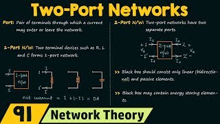
Introduction & Overview
Read summaries of the section's main ideas at different levels of detail.
Quick Overview
Standard
Key equations in this section include formulas for determining the quality factor of L-section components and calculating the length of an open-circuit stub in matching networks. These equations are pivotal for achieving optimal impedance matching in RF applications.
Detailed
Detailed Summary
In this section, we focus on Key Equations that are fundamental to the design of matching networks in two-port networks. These equations serve as foundational tools for engineers working with RF amplifiers and similar applications. Key equations include:
- L-Section Components: The quality factor (
Q) is given by
$$ Q = \sqrt{\frac{R_{high}}{R_{low}} - 1} $$
This equation allows for the selection of the appropriate reactance values to optimize the matching network's efficiency.
- Stub Length (Open-Circuit): The length of an open-circuit stub can be derived from the equation:
$$ l = \frac{\lambda}{2\pi} \tan^{-1}\left(\frac{B}{Y_0}\right) $$
This is crucial for adjusting the reactance in the matching network to minimize reflections and enhance power transfer. Understanding these equations is essential for effectively designing matching networks and ensuring optimal performance in RF systems.
Youtube Videos

Audio Book
Dive deep into the subject with an immersive audiobook experience.
L-Section Components
Chapter 1 of 2
🔒 Unlock Audio Chapter
Sign up and enroll to access the full audio experience
Chapter Content
- L-Section Components:
\[ Q = \sqrt{\frac{R_{high}}{R_{low}} - 1} \]
Detailed Explanation
This equation represents the quality factor (Q) of an L-section matching network. The quality factor is a dimensionless parameter that describes how underdamped a resonator or circuit is, which can be thought of as a measure of the energy loss relative to the stored energy. Here, R_high is the higher resistance value in the matching network, and R_low is the lower resistance. If we increase R_high or decrease R_low, Q will increase, indicating better performance of the matching network with lower losses.
Examples & Analogies
Imagine a water reservoir where R_high is the size of a large tank and R_low is the size of a small bucket. If you have a large tank (R_high) and a small bucket (R_low), the tank stores a lot more water compared to the bucket, making it easier to maintain high water levels (energy) with less spillage (loss). Hence, in a matching network, having a higher R_high over R_low will improve the circuit's efficiency, just like having a larger tank reduces spill-over.
Stub Length (Open-Circuit)
Chapter 2 of 2
🔒 Unlock Audio Chapter
Sign up and enroll to access the full audio experience
Chapter Content
- Stub Length (Open-Circuit):
\[ l = \frac{\lambda}{2\pi} \tan^{-1}\left(\frac{B}{Y_0}\right) \]
Detailed Explanation
This equation is used to calculate the length of an open-circuit stub in a matching network, which is essential for impedance matching. The variable \( l \) represents the length of the stub, \( \lambda \) is the wavelength of the signal, \( B \) is the susceptance of the load, and \( Y_0 \) is the admittance of the system. The stub helps in canceling the unwanted reactance from the load to match the desired impedance. The angle from the arctangent function indicates how much the stub needs to adjust the phase to achieve an appropriate match.
Examples & Analogies
Think of the stub as an adjustable arm on a balance scale. Just as you'd adjust the arm to balance weights on both sides, you're adjusting the stub length to ensure that when signals hit the load, they are perfectly in sync (i.e., matched). If the arm (stub) is too short or too long, it will tip the scale, leading to ineffective matching and potential energy loss.
Key Concepts
-
L-Section Components: Important for determining quality factor in matching networks.
-
Stub Length: Essential for calculating correct physical dimensions for impedance matching.
-
Susceptance: Represents how reactive components affect current flow.
-
Characteristic Admittance: Defining ratio for signal propagation in transmission lines.
Examples & Applications
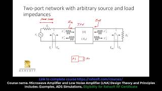
To achieve an optimal match between a 75 Ω load and a 50 Ω source, the corresponding quality factor, Q, can be computed using the defined equation, allowing for the selection of suitable reactance.
When designing a stub matching network, one must calculate the stub length accurately using the stub length equation to ensure efficient power transfer.
Memory Aids
Interactive tools to help you remember key concepts
Rhymes
When the quality we seek, use Q as our peak, divided by lows, let the power flows.
Stories
Imagine a builder measuring lengths of wood. Just like he needs the right size for strength, in RF, the stub length is measured to ensure the signal is strong too!
Memory Tools
To remember the quality factor, think 'Q is Quiet' - it minimizes noise in our signals.
Acronyms
For stub length, remember SL for 'Stub Length'
means measuring length with care.
Flash Cards
Glossary
- Quality Factor (Q)
A dimensionless parameter that describes the dampening of a resonator, indicating howunder-damped an oscillator or resonator is.
- Stub Length
The physical length of a transmission line used to create a specific reactance in matching networks.
- Susceptance (B)
The imaginary part of admittance, representing the ease with which an electric current flows in a circuit due to reactive components.
- Characteristic Admittance (Y0)
The ratio of voltage to current for a transmission line, which determines how signals propagate within the line.
Reference links
Supplementary resources to enhance your learning experience.