
Practical Considerations
Interactive Audio Lesson
Listen to a student-teacher conversation explaining the topic in a relatable way.
Component Losses
🔒 Unlock Audio Lesson
Sign up and enroll to listen to this audio lesson

Today, we're going to talk about component losses in matching networks. What do you think the effective Q-factor indicates?

Is it related to how well the network can transfer power without losing too much signal?
Exactly! The effective Q-factor tells us how much energy is lost versus how much is retained. The formula for effective Q-factor is given by: Q_eff = f_0 / BW. Can anyone tell me why this is important?

It helps us design better matching networks, right? If we know the losses, we can make adjustments.
Great point! It's crucial for high-frequency applications due to the increased impact of losses. Let’s not forget the relationship: \[ Q_{eff} \leq \frac{1}{2} \sqrt{\frac{R_{high}}{R_{low}} - 1} \] which indicates the limits of our designs. Remember, higher Q factors mean less energy loss.

So lower losses mean better performance, especially at higher frequencies?
Exactly, that's the core idea! Reducing losses makes our networks much more efficient.
PCB Layout Effects
🔒 Unlock Audio Lesson
Sign up and enroll to listen to this audio lesson

Next, let’s explore how PCB layout affects our matching networks. What are some specific issues that we might encounter?

I’ve heard about trace inductance and pad capacitance. How do those impact our designs?
That's a great start! Trace inductance is around ~1nH/mm, while pad capacitance can be ~0.1pF. These parasitics can change the performance of a circuit significantly. Can anyone explain how?
I think they can add unwanted reactance, which would mess up the impedance matching, right?
Correct! Unwanted reactance can create mismatches in the network. It's vital to factor in these elements during the design process.
So, testing the actual layout is as important as theoretical calculations?
Absolutely. Practical testing can reveal surprises that theory may overlook. Always prototype and test!
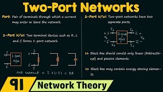
Introduction & Overview
Read summaries of the section's main ideas at different levels of detail.
Quick Overview
Standard
In the realm of two-port network design, 'Practical Considerations' addresses two crucial aspects: component losses and PCB layout effects. The effective Q-factor and how parasitic elements, such as trace inductance and pad capacitance, can impact the performance of matching networks are explored.
Detailed
Practical Considerations
Component Losses
The effective Q-factor is defined as:
\[ Q_{eff} = \frac{f_0}{BW} \leq \frac{1}{2} \sqrt{\frac{R_{high}}{R_{low}} - 1} \]
This equation reflects the consideration of component losses that can guide engineers in designing more efficient impedance matching networks. In practical scenarios, the Q-factor can greatly influence the performance of the matching network, particularly in high-frequency applications where loss becomes a significant factor.
PCB Layout Effects
Another critical point in practical design considerations is the effect of PCB layout, particularly parasitics which can include trace inductance and pad capacitance. For example, the trace inductance can be approximated as ~1nH/mm while pad capacitance can be about ~0.1pF.
These parasitic elements can introduce unwanted reactances that affect the ideal characteristics of the matching network, thus influencing overall performance. Real-world application of matching networks must consider these parameters to achieve optimal performance in impedance matching.
Youtube Videos


Audio Book
Dive deep into the subject with an immersive audiobook experience.
Component Losses
Chapter 1 of 2
🔒 Unlock Audio Chapter
Sign up and enroll to access the full audio experience
Chapter Content
10.6.1 Component Losses
- Effective Q-Factor:
\[
Q_{eff} = \frac{f_0}{BW} \leq \frac{1}{2} \sqrt{\frac{R_{high}}{R_{low}} - 1}
\]
Detailed Explanation
In this section, we discuss component losses, which are crucial for understanding the performance of matching networks. The effective Q-factor is a measure of the quality of resonant circuits in the context of their bandwidth and quality. The formula provided calculates the effective quality factor (Q_eff), which indicates how much energy is lost relative to what is stored in the reactive components of the network. The term 'BW' refers to the bandwidth over which the circuit operates effectively, while 'f_0' is the center frequency of the circuit. This equation shows that higher 'R_high' to 'R_low' ratios lead to a higher effective Q-factor, meaning less energy is lost, thus improving performance. However, if the ratio is not favorable, the losses escalate, resulting in poor performance for the network.
Examples & Analogies
Consider the effective Q-factor similar to a tuning fork used in music. If the fork is finely crafted (high R_high), it vibrates beautifully for a longer duration (high Q-factor). However, if it's poorly made (low R_low), it dampens quickly and loses its sound (high losses). Just like in a matching network, having a good balance between the high and low resistance helps in maximizing sound quality, akin to maximizing power transfer in electrical circuits.
PCB Layout Effects
Chapter 2 of 2
🔒 Unlock Audio Chapter
Sign up and enroll to access the full audio experience
Chapter Content
10.6.2 PCB Layout Effects
- Parasitics:
- Trace inductance (~1nH/mm).
- Pad capacitance (~0.1pF).
Detailed Explanation
This section highlights the effects of printed circuit board (PCB) layouts on the performance of matching networks due to parasitic elements. Parasitic inductance and capacitance are unintended effects that occur in real circuits, differing from ideal conditions. Trace inductance refers to the electrical properties that arise from the metallic paths on the PCB, roughly estimated at ~1nH for every millimeter. This inductance can introduce delays and reflections, degrading the matching network's performance. Likewise, pad capacitance, estimated at ~0.1pF, results from the pads where components are soldered, impacting the overall impedance of the network. Understanding these effects is crucial for design considerations to minimize losses and optimize performance.
Examples & Analogies
Think of PCB layout effects like the 'traffic conditions' in a busy city. Just as too many cars (parasitics) can slow down traffic flow, causing delays and congestion, trace inductance and pad capacitance can disrupt the ideal flow of electrical signals in a circuit. A well-planned route, much like a well-designed PCB layout, ensures smooth flow with minimal interruptions, allowing for better overall performance.
Key Concepts
-
Q-Factor: The ratio of resonant frequency to bandwidth, indicative of energy losses.
-
Component Losses: Losses that occur in the system due to non-ideal components.
-
PCB Layout: The arrangement of components on a PCB which affects performance due to parasitic elements.
Examples & Applications
When designing an RF amplifier, ignoring trace inductance could lead to significant degradation in performance.
Testing the layout of a matching network reveals that unforeseen pad capacitance can distort expected behavior.
Memory Aids
Interactive tools to help you remember key concepts
Rhymes
To keep Q high, we must try, lessen losses, no need to cry!
Stories
Once, an engineer designed a PCB without considering trace length. It turned into a disaster, as the trace inductance ruined the signal.
Memory Tools
P.C. - Parasitics Considerations: trace leads to unknown deviations!
Acronyms
ECHO
Evaluate Component losses
High-frequency Orientation
Flash Cards
Glossary
- Effective QFactor
A measure of the quality of a resonant circuit, indicative of energy loss relative to the stored energy.
- Trace Inductance
The inductance associated with PCB trace paths, which can introduce unwanted reactance.
- Pad Capacitance
The capacitance associated with the pads used to connect components on a PCB.
Reference links
Supplementary resources to enhance your learning experience.