
YOUNG’S INTERFERENCE OF LIGHT WAVES AND YOUNG'S EXPERIMENT
Enroll to start learning
You’ve not yet enrolled in this course. Please enroll for free to listen to audio lessons, classroom podcasts and take practice test.
Interactive Audio Lesson
Listen to a student-teacher conversation explaining the topic in a relatable way.
Understanding Coherence in Light Waves
🔒 Unlock Audio Lesson
Sign up and enroll to listen to this audio lesson

Today, we will explore Young’s interference experiment. But first, what does it mean for light sources to be coherent?

Does that mean they are in phase?
Exactly! Coherent sources have a constant phase difference. For example, if we use two sodium lamps, why wouldn't we see interference?

Because they're not coherent? They have abrupt phase changes!
Right! Abrupt phase changes mean the light from those sources can’t interfere constructively or destructively. So, Young used pinholes from a single source to create coherence.

That sounds smart! So, how does he actually see the interference on the screen?
Great question! The light waves spread out from the two pinholes and overlap, creating alternating patterns of light and dark on the screen due to constructive and destructive interference.
In summary, coherence is crucial for seeing the interference pattern. Are there any questions before we move on?
Exploring the Concept of Interference
🔒 Unlock Audio Lesson
Sign up and enroll to listen to this audio lesson

Now, let's break down how interference leads to those bright and dark fringes. Can anyone tell me what causes constructive interference?

When the path difference is a whole number of wavelengths, right?
Exactly! And for dark fringes, what happens?
That would be when the path difference is half a wavelength!
Correct! So, if we set n as a variable for the number of wavelengths, how can we express the positions of bright and dark fringes mathematically?
The formulas we use are x = nλD/d for bright fringes and x = (n + 1/2)λD/d for dark fringes!
Well done! These equations help us calculate where to find those interference fringes on the screen.
As a summary, constructive interference is when the path difference equals n wavelengths, while destructive interference is when it's (n + 0.5) wavelengths. Great work!
Practical Applications of Young's Experiment
🔒 Unlock Audio Lesson
Sign up and enroll to listen to this audio lesson
Young's experiment is more than just a physics demonstration; it shows waves can interfere. Can anyone think of practical uses for this concept?
Maybe in measuring distances or wavelengths?
Absolutely! Interference patterns can help in determining the wavelength of light, which is crucial in many optical applications.
And isn't that how certain types of lasers and sensors work too?
Yes, you're spot on! Lasers utilize interference in their operation, and sensors can use the principles of interference to measure tiny displacements.
To summarize our discussion, Young’s interferometry serves not only as a proof of wave behavior but also as a tool in technological applications.
Introduction & Overview
Read summaries of the section's main ideas at different levels of detail.
Quick Overview
Standard
Young's experiment used a coherent light source to produce interference patterns through two closely spaced pinholes, proving that light behaves as a wave. Constructive and destructive interference lead to alternating bright and dark fringes on the screen, illustrating the principle of superposition.
Detailed
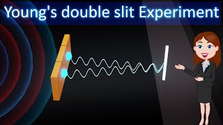
In this section, we explore Thomas Young's double-slit experiment, which fundamentally demonstrated that light exhibits wave-like characteristics. The experiment involves illuminating two closely spaced pinholes (S1 and S2) with light from a single coherent source. The light waves emerging from these pinholes spread out and overlap, leading to an interference pattern on a screen due to the principles of constructive and destructive interference. Constructive interference occurs when the path length difference between the two waves is an integer multiple of the wavelength, resulting in bright fringes. Conversely, destructive interference takes place when the path length difference is a half-integer multiple of the wavelength, leading to dark fringes. These fringe patterns are a critical evidence for the wave theory of light and allow calculating the wavelength of light and the spacing between fringes.
Youtube Videos


Audio Book
Dive deep into the subject with an immersive audiobook experience.
Incoherence of Ordinary Light Sources
Chapter 1 of 4
🔒 Unlock Audio Chapter
Sign up and enroll to access the full audio experience
Chapter Content
If we use two sodium lamps illuminating two pinholes, we will not observe any interference fringes. This is because of the fact that the light wave emitted from an ordinary source (like a sodium lamp) undergoes abrupt phase changes in times of the order of 10–10 seconds. Thus the light waves coming out from two independent sources of light will not have any fixed phase relationship and would be incoherent.
Detailed Explanation
Ordinary light sources, like sodium lamps, emit light waves that rapidly change phase. This means that the light waves produced from two different sources (in this case, the sodium lamps) do not maintain a constant relationship in their phase. Since interference depends on having coherent light sources—where phase relationships are stable and predictably aligned—no interference pattern will be observed from these lamps. This can be likened to two singers trying to harmonize; if they sing at different rhythms or pitches that continually changes, they won't create a harmonious tune, similar to how incoherent light sources fail to produce an interference pattern.
Examples & Analogies
Imagine trying to create a perfect echo at a concert by using two speakers. If both speakers produce sounds that change unpredictably, there will be no clear or recognizable echo. Similarly, when two sodium lamps illuminate pinholes, their light waves become incoherent and thus no clear interference fringes are formed.
Young's Ingenious Technique
Chapter 2 of 4
🔒 Unlock Audio Chapter
Sign up and enroll to access the full audio experience
Chapter Content
The British physicist Thomas Young used an ingenious technique to “lock” the phases of the waves emanating from S1 and S2. He made two pinholes S1 and S2 (very close to each other) on an opaque screen. These were illuminated by another pinhole that was in turn, lit by a bright source. Light waves spread out from S and fall on both S and S. S1 and S2 then behave like two coherent sources because light waves coming out from S1 and S2 are derived from the same original source.
Detailed Explanation
To achieve a stable and coherent light source, Young created two closely spaced pinholes, S1 and S2, which were illuminated by a single bright source. This ensured that the waves emanating from both pinholes would maintain a constant phase relationship, making them behave like coherent sources. This clever setup allowed for the observation of interference patterns on a screen due to the overlapping waves from the two sources. This is akin to having two musical instruments that play the same note; if they start together and continue without any interruptions, they will always produce a harmonious sound.
Examples & Analogies
Think of a marching band where two different groups of musicians are supposed to play in sync. If they all look at the same conductor, they are more likely to stay in sync together, producing a beautiful melody. In Young's experiment, the single light source acts as the conductor, ensuring that both pinholes produce coherent light waves.
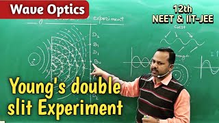
Formation of Interference Fringes
Chapter 3 of 4
🔒 Unlock Audio Chapter
Sign up and enroll to access the full audio experience
Chapter Content
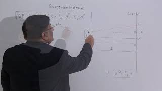
The spherical waves emanating from S1 and S2 produce interference fringes on the screen GG’, as shown in Figure 10.12(b). The positions of maximum and minimum intensities can be calculated by using the analysis given in Section 10.4.
Detailed Explanation
When the coherent light waves from the two pinholes converge on a screen, they interact with each other, leading to areas of constructive interference (where waves add together to create bright fringes) and destructive interference (where waves cancel each other out, creating dark fringes). The specific positions of these bright and dark bands can be accurately predicted using equations that relate to the path differences the light waves travel before they reach the screen. This analysis is crucial in preventing randomness, allowing us to consistently observe and measure the interference patterns.
Examples & Analogies
Consider a swimming pool where two swimmers are diving into the pool at the same time from opposite ends. As they create waves in the water, where those waves meet, they might either amplify each other (making bigger waves) or cancel each other out (making calmer areas). In Young's experiment, the light waves are like the swimmers, combining in the right conditions to create the patterns we can see.
Calculating Interference Patterns
Chapter 4 of 4
🔒 Unlock Audio Chapter
Sign up and enroll to access the full audio experience
Chapter Content
We will have constructive interference resulting in a bright region when x = nλD/d; n = 0, ±1, ±2,… On the other hand, we will have destructive interference resulting in a dark region when x = (n + 1/2) λD/d.
Detailed Explanation
The fringe patterns produced in Young's interference experiment can be quantitatively described using specific formulas. When the path difference between waves from the two pinholes is a whole number of wavelengths (nλ), a bright fringe occurs—this is known as constructive interference. Conversely, when the path difference is a half number of wavelengths (n + 1/2)λ, the waves cancel each other out, leading to dark fringes, known as destructive interference. These equations are derived from the geometry of the setup and the properties of wave interference.
Examples & Analogies
Imagine setting up a series of dominoes where every time two groups of dominoes fall in sync, they create a big noise (constructive interference), but at other moments, when they fall at slightly different times, they may just cancel each other out. The interference pattern with bright and dark spots is similar to the resulting sounds from falling dominoes at different times.
Key Concepts
-
Interference: The phenomenon where two or more waves combine to form a new wave pattern.
-
Coherence: The condition where two sources emit waves with a fixed phase relationship, essential for interference.
-
Path Difference: The difference between the distances traveled by two waves from their sources to a point on the screen.
Examples & Applications
In Young's double-slit experiment, light from a single coherent source illuminates two pinholes, leading to an interference pattern on the screen.
The concept of constructive and destructive interference can be illustrated using sound waves from two speakers to create a similar interference pattern.
Memory Aids
Interactive tools to help you remember key concepts
Rhymes
When waves meet in the right way, bright bands appear, it’s a beautiful display!
Stories
Imagine two friends throwing pebbles into a pond. If the waves hit the right way, they either make a bigger splash or they cancel each other out, forming still water in some parts.
Memory Tools
C for Constructive and D for Destructive - remember: Constructive is when they add up, Destructive when they split up!
Acronyms
C-D formula for fringe spacing
for Constructive
for Destructive (n for integer
n+0.5 for half-integer).
Flash Cards
Glossary
- Coherent Sources
Light sources that maintain a constant phase difference, essential for observing interference patterns.
- Constructive Interference
Occurs when two overlapping waves reinforce each other, resulting in increased amplitude and brightness.
- Destructive Interference
Occurs when two overlapping waves cancel each other out, resulting in decreased amplitude and darkness.
- Interference Fringe
The alternating patterns of light and dark created on a screen due to interference of waves.
- Path Difference
The difference in distance traveled by two waves from their sources to a common point.
Reference links
Supplementary resources to enhance your learning experience.