
Basic Operation of NMOS and PMOS Transistors
Enroll to start learning
You’ve not yet enrolled in this course. Please enroll for free to listen to audio lessons, classroom podcasts and take practice test.
Interactive Audio Lesson
Listen to a student-teacher conversation explaining the topic in a relatable way.
Introduction to NMOS Transistor Behavior
🔒 Unlock Audio Lesson
Sign up and enroll to listen to this audio lesson

Today, we are going to talk about NMOS transistors. Can anyone tell me how an NMOS transistor operates?

Does it conduct when the voltage is high?
Exactly! NMOS transistors conduct current when a positive gate-source voltage, or VGS, exceeds the threshold voltage, known as Vth. Can anyone explain what happens when VGS is less than Vth?

Then the transistor is off and no current flows, right?
Correct! This is called the cutoff region. Remember: 'Cutoff is out, VGS must shout!' When VGS is above Vth, we have linear and saturation regions. Who wants to dive deeper into those?

I do! What are the linear and saturation regions?
Great question! In the linear region, the NMOS behaves like a resistor, and in the saturation region, the current primarily depends on VGS and not VDS. Can someone tell me what the equation for drain current in saturation is?

Is it ID = (1/2) * Kn * (VGS - Vth)² * (1 + λVDS)?
Yes! Fantastic job! That's key to understanding how NMOS transistors behave in circuits. Let's summarize: NMOS turns on with a positive VGS, has three regions of operation, and its drain current can be calculated using that equation. Any final questions?
PMOS Transistor Behavior
🔒 Unlock Audio Lesson
Sign up and enroll to listen to this audio lesson

Now that we've covered NMOS, let's shift gears to PMOS transistors. Who can share how a PMOS transistor operates?
It works with negative voltage?
Exactly! PMOS transistors turn on when the gate-source voltage (VGS) is negative enough, below the threshold voltage. What can you tell me about the regions of operation?
It has cutoff, linear, and saturation just like NMOS, but they work differently, right?
Correct! In PMOS, cutoff happens when VGS is above Vth. In linear, it behaves like a resistor, and in saturation, VGS controls the current predominantly. Can anyone tell me the equation for the drain current in saturation?
Isn't it ID = (1/2) * Kp * (VSG - |Vth|)² * (1 + λVDS)?
Exactly right! Again, Kp is critical here. Comparing both types, remember: 'Positive for NMOS, negative for PMOS'. Excellent work today, everyone!
Comparison of NMOS and PMOS
🔒 Unlock Audio Lesson
Sign up and enroll to listen to this audio lesson
Let’s compare NMOS and PMOS transistors. Why do we need both in CMOS technology?
They work together to reduce power consumption?
Absolutely! When one is on, the other is off, minimizing static power consumption. Can anyone summarize the key differences in operation?
NMOS conducts with positive VGS and PMOS with negative VGS, right?
Right! Vth is positive for NMOS and negative for PMOS, which directly affects how they operate. Who remembers how the I-V characteristics look different for both?
They’re both quadratic but with different parameters, right?
Perfect! That’s an excellent way to think about it. Remember, their complementary operation makes CMOS efficient! Great discussion today!
Introduction & Overview
Read summaries of the section's main ideas at different levels of detail.
Quick Overview
Standard
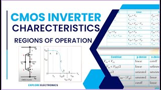
In this section, we discuss the fundamental operations of NMOS and PMOS transistors in CMOS technology, detailing their threshold voltages, operation regions (cutoff, linear, saturation), and I-V characteristics. Understanding these concepts is essential for grasping CMOS circuit design and performance.
Detailed
Basic Operation of NMOS and PMOS Transistors
The operation of CMOS devices hinges on the complementary functioning of NMOS and PMOS transistors. NMOS transistors conduct when a sufficiently positive gate-source voltage (VGS) is applied, while PMOS transistors conduct when VGS is negative. Each type of transistor features a critical threshold voltage (Vth), below which it remains off.
NMOS Transistor Behavior
- Threshold Voltage (Vth): The minimum gate voltage required for conduction.
- Operation Regions:
- Cutoff Region: VGS < Vth, transistor is off.
- Linear Region: VGS > Vth with small VDS, behaves like a resistor.
- Saturation Region: VGS > Vth with large VDS, current primarily depends on VGS.
- I-V Characteristics: The drain current (ID) in saturation is expressed as:
ID = (1/2) * Kn * (VGS - Vth)² * (1 + λVDS), where Kn is a process-dependent constant and λ is the channel-length modulation factor.
PMOS Transistor Behavior
- Threshold Voltage (Vth): Typically negative, the transistor turns on when VGS is below Vth.
- Operation Regions:
- Cutoff Region: VGS > Vth, transistor is off.
- Linear Region: Sufficiently negative VGS with small VDS, behaves like a resistor.
- Saturation Region: Negative VGS and large VDS, similar current control as NMOS.
- I-V Characteristics: Drain current (ID) in the saturation region is given by:
ID = (1/2) * Kp * (VSG - |Vth|)² * (1 + λVDS), where Kp is the process-dependent constant for PMOS.
Understanding these operational principles is critical for effective CMOS circuit design, affecting everything from power consumption to performance.
Youtube Videos
Audio Book
Dive deep into the subject with an immersive audiobook experience.
Introduction to NMOS and PMOS Transistors
Chapter 1 of 7
🔒 Unlock Audio Chapter
Sign up and enroll to access the full audio experience
Chapter Content
The operation of CMOS devices is based on the interaction between NMOS and PMOS transistors. These devices are designed to operate in complementary modes, meaning when one transistor is on, the other is off, ensuring minimal static power consumption.
Detailed Explanation
CMOS devices rely on the combination of NMOS and PMOS transistors to function effectively. NMOS transistors conduct when the gate voltage is high, while PMOS transistors conduct when the gate voltage is low. This complementary operation is important because it allows the circuit to reduce power consumption when not in use, preventing both transistors from conducting simultaneously, which would waste energy.
Examples & Analogies
Imagine turning on a light bulb while at the same time ensuring the switch for a ceiling fan is off. In this scenario, the light bulb represents the NMOS transistor, which needs a positive signal (like flipping a switch) to turn on, and the ceiling fan represents the PMOS transistor, which must be off to prevent energy waste. This balance helps in consuming less electricity.
NMOS Transistor Behavior
Chapter 2 of 7
🔒 Unlock Audio Chapter
Sign up and enroll to access the full audio experience
Chapter Content
An NMOS transistor has an n-type channel that conducts current when a positive voltage is applied to the gate relative to the source (known as gate-source voltage, or VGS).
Detailed Explanation
The NMOS transistor operates based on the gate-source voltage (VGS). When this voltage exceeds a specific level called the threshold voltage (Vth), a conductive channel is formed, allowing current to flow from the drain to the source. This active state is divided into distinct operational regions: cutoff, linear, and saturation, each with specific characteristics and applications.
Examples & Analogies
Think of a water faucet. The amount of water that flows out relates to how far you turn the handle (which is like increasing the VGS). If you barely turn the handle, no water flows (cutoff region). If you turn it just right, water flows steadily (linear region), and if you turn it all the way, the flow remains steady regardless of how much more you try to turn (saturation region).
Operation Regions of NMOS
Chapter 3 of 7
🔒 Unlock Audio Chapter
Sign up and enroll to access the full audio experience
Chapter Content
● Cutoff Region: When VGS is less than Vth, the NMOS transistor is off, and no current flows from the drain to the source.
● Linear/Ohmic Region: When VGS > Vth and the drain-source voltage VDS is small, the NMOS transistor behaves like a resistor, and current flows linearly with VDS.
● Saturation Region: When VGS > Vth and VDS is large, the NMOS enters saturation. Here, the current is primarily controlled by VGS and is relatively independent of VDS.
Detailed Explanation
The NMOS transistor has three operation regions: Cutoff, where it does not allow current to pass (off state); Linear, where it behaves like a simple resistor allowing current to pass proportionally to the voltage; and Saturation, where it allows maximum current flow, mainly dependent on the gate voltage and less on the drain-source voltage. Understanding these regions is critical for designing effective circuits.
Examples & Analogies
Consider a water pipe with varying flow rates based on the faucet's turning. In the cutoff region, the faucet is almost closed, so no water flows. In the linear region, as you open the faucet slightly, more water flows (but the increase is directly related to how much you turn it). In the saturation region, opening the faucet fully gets you maximum flow, but additional turns do not significantly increase the flow rate.
I-V Characteristics of NMOS Transistor
Chapter 4 of 7
🔒 Unlock Audio Chapter
Sign up and enroll to access the full audio experience
Chapter Content
The drain current (ID) in the saturation region is given by:
ID = 12Kn(VGS−Vth)2(1+λVDS), where Kn is the process-dependent constant, λ is the channel-length modulation factor, VGS is the gate-source voltage, and Vth is the threshold voltage.
Detailed Explanation
The drain current in the saturation region is determined by a specific formula that incorporates several factors: the gate-source voltage (VGS), the threshold voltage (Vth), and constants that depend on the manufacturing process. This equation shows how changes in the gate voltage affect current flow, which is crucial for understanding performance in circuit designs.
Examples & Analogies
Imagine baking a cake, where the ingredients (like VGS, Vth, and Kn) interact to create the final product (ID). Just as changing the amount of sugar or flour affects how the cake turns out, adjusting VGS will influence how much current flows through the NMOS transistor.
PMOS Transistor Behavior
Chapter 5 of 7
🔒 Unlock Audio Chapter
Sign up and enroll to access the full audio experience
Chapter Content
A PMOS transistor has a p-type channel and is controlled by a negative gate-source voltage. The PMOS transistor conducts current when the gate voltage is lower than the source voltage (i.e., VGS < Vth).
Detailed Explanation
Like NMOS, the PMOS transistor has a threshold voltage, but it operates differently. The VGS must be negative to turn on the transistor. In essence, the PMOS conducts when the gate voltage drops below a certain level, allowing current to flow from the source to the drain, working in opposition to the NMOS.
Examples & Analogies
Consider a seesaw that lifts children into the air when pushed down on one side. Here, pushing down corresponds to applying a negative voltage on the PMOS transistor. When the side with the child is pressed down (i.e., the gate is pulled below the threshold), the child goes up, similar to current flowing in a PMOS transistor when it’s activated.
Operation Regions of PMOS
Chapter 6 of 7
🔒 Unlock Audio Chapter
Sign up and enroll to access the full audio experience
Chapter Content
● Cutoff Region: When VGS is above Vth, the PMOS transistor is off, and no current flows.
● Linear/Ohmic Region: When VGS is sufficiently negative, and VDS is small, the PMOS behaves like a resistor, and current flows linearly with VDS.
● Saturation Region: When VGS is negative enough and VDS is large, the PMOS transistor enters the saturation region, where the current is primarily controlled by VGS.
Detailed Explanation
The PMOS transistor also has three regions of operation: Cutoff, where it does not conduct (like the NMOS); Linear, where it acts as a resistor allowing controlled current flow; and Saturation, where it allows maximum flow, mainly driven by negative gate voltage. Each of these operational regions is crucial for circuit design and understanding how PMOS transistors contribute to system functionality.
Examples & Analogies
Taking the example of a seesaw again: in the Cutoff region, no one is on the seesaw, and it doesn’t move. As someone gets on, it becomes easier to lift the other end (Linear region). If the person jumps up, the seesaw shoots the other child up quickly - that simultaneous maximum lift of both ends is like the PMOS transistor in saturation.
I-V Characteristics of PMOS Transistor
Chapter 7 of 7
🔒 Unlock Audio Chapter
Sign up and enroll to access the full audio experience
Chapter Content
The drain current (ID) in the saturation region for PMOS is given by:
ID = 12Kp(VSG−|Vth|)2(1+λVDS), where Kp is the process-dependent constant for PMOS, λ is the channel-length modulation factor, VSG is the source-gate voltage, and |Vth| is the magnitude of the threshold voltage.
Detailed Explanation
Similar to the NMOS, the drain current in the saturation region for the PMOS transistor is also defined by a specific equation. This equation relates the source-gate voltage and the threshold voltage to the current flowing through the PMOS. Understanding this formula is essential for examining PMOS performance in electronic circuits.
Examples & Analogies
Think of a well-organized library. The amount of resources (like books on a shelf) can change based on how many books are actively organized and retrieved (akin to the voltage parameters). The more focused the activity of organizing, the more resources can be utilized efficiently, just like how current flows based on the gate voltages in PMOS transistors.
Key Concepts
-
Threshold Voltage (Vth): The minimum voltage required for a transistor to turn on.
-
NMOS Operation: Conducts with positive VGS; operates in cutoff, linear, and saturation regions.
-
PMOS Operation: Conducts with negative VGS; operates in cutoff, linear, and saturation regions.
-
I-V Characteristics: The mathematical relation of current with voltage in different regions.
Examples & Applications
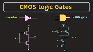
An NMOS transistor is used in a CMOS inverter circuit where it pulls the output low when activated.
In a PMOS transistor, a negative gate-source voltage is applied to turn it on when connected in a complementary configuration.
Memory Aids
Interactive tools to help you remember key concepts
Rhymes
NMOS will glow with a positive flow, PMOS will show when negative you throw.
Stories
Imagine two friends: NMOS loves positive vibes and turns on with them, while PMOS prefers the negative and opens up when it's down.
Memory Tools
Remember 'N for Negative' for the PMOS is a common mistake; it's actually 'P for Positive' with NMOS working when VGS is high.
Acronyms
Remember 'C-L-S' for Cutoff, Linear, Saturation regions in NMOS and PMOS operation.
Flash Cards
Glossary
- NMOS Transistor
A type of MOSFET that conducts when the gate-source voltage is positive.
- PMOS Transistor
A type of MOSFET that conducts when the gate-source voltage is negative.
- Threshold Voltage (Vth)
The minimum gate voltage necessary to form a conductive channel between source and drain.
- Drain Current (ID)
The current that flows from the drain to the source in a MOSFET.
- ChannelLength Modulation
A phenomenon where the effective channel length of a MOSFET changes with the applied drain-source voltage.
Reference links
Supplementary resources to enhance your learning experience.