
Summary of Key Concepts
Enroll to start learning
You’ve not yet enrolled in this course. Please enroll for free to listen to audio lessons, classroom podcasts and take practice test.
Interactive Audio Lesson
Listen to a student-teacher conversation explaining the topic in a relatable way.
NMOS and PMOS Transistors
🔒 Unlock Audio Lesson
Sign up and enroll to listen to this audio lesson

Today, we're going to explore NMOS and PMOS transistors, the backbone of CMOS technology. Does anyone know when an NMOS transistor turns on?

Is it when the gate-source voltage is greater than the threshold voltage?
Exactly! We can remember that with the acronym 'G-T' for Gate exceeds Threshold. Now, who can tell me when a PMOS transistor operates?

It works when the gate-source voltage is below the threshold, right?
Correct! So, to summarize: NMOS conducts when VGS > Vth and PMOS conducts when VGS < Vth. Great job!
CMOS Inverter
🔒 Unlock Audio Lesson
Sign up and enroll to listen to this audio lesson

Now, let's discuss the CMOS inverter. What happens when the input is high?

The NMOS transistor turns on, and the output goes low.
Exactly! And if the input is low?

Then the PMOS transistor turns on, and the output goes high!
Great! This complementary action is what allows the inverter to function efficiently with low power consumption. Let's keep this in mind as we move forward!
Channel-Length Modulation
🔒 Unlock Audio Lesson
Sign up and enroll to listen to this audio lesson
Let's look at channel-length modulation. One of you tell me, how does the effective length of a MOSFET channel change with the drain-source voltage?
It changes because, as the voltage increases, the length can effectively decrease, impacting current flow.
That's right! This effect is small in long-channel devices but can be significant in short-channel devices. Can anyone summarize its impact?
It modifies the drain current in saturation.
Exactly! This is crucial for understanding modern CMOS performance.
Threshold Voltage Variations
🔒 Unlock Audio Lesson
Sign up and enroll to listen to this audio lesson
Now let's talk about the threshold voltage, Vth. Can anyone name some factors that affect it?
Temperature changes can affect it, right?
Correct! And what else?
Process variations during fabrication, and biases too!
Exactly! Keeping these effects in mind is vital when designing reliable CMOS circuits. Remember that Vth is critical for switching behavior!
Introduction & Overview
Read summaries of the section's main ideas at different levels of detail.
Quick Overview
Standard
The summary outlines key features of NMOS and PMOS transistors, explains the operation of CMOS inverters, describes channel-length modulation, and discusses subthreshold and superthreshold operations. It emphasizes the importance of threshold voltage and the factors affecting it.
Detailed
Summary of Key Concepts
The CMOS technology is centered around two primary transistor types: NMOS and PMOS. NMOS transistors become conductive when the gate-source voltage exceeds a certain threshold, allowing current flow from drain to source. Conversely, PMOS transistors activate under negative gate-source voltage, where current flows from source to drain. The complementary operation of these transistors forms the basis of CMOS inverters, which efficiently invert input signals while minimizing power consumption.
Additionally, the chapter discusses channel-length modulation, highlighting how variations in drain-source voltage affect current in saturation. Furthermore, it explains subthreshold operation, where transistors can conduct at voltages below the threshold, and superthreshold operation, where normal current flow occurs above this threshold. The threshold voltage itself is influenced by various factors, including fabrication processes and temperature. Understanding these concepts is crucial for grasping the functioning of modern electronic circuits that rely on CMOS technology.
Youtube Videos
Audio Book
Dive deep into the subject with an immersive audiobook experience.
NMOS and PMOS Transistors
Chapter 1 of 5
🔒 Unlock Audio Chapter
Sign up and enroll to access the full audio experience
Chapter Content
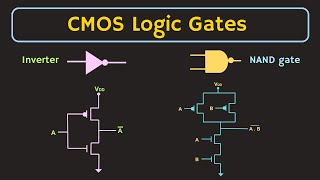
● NMOS and PMOS Transistors: The core components of CMOS devices. NMOS transistors conduct when the gate-source voltage is above the threshold, while PMOS transistors conduct when the gate-source voltage is below the threshold.
Detailed Explanation
This chunk highlights the fundamental components of CMOS devices: NMOS and PMOS transistors. An NMOS transistor operates when the voltage at its gate (the part that controls it) is higher than a certain threshold. Similarly, a PMOS transistor works when the gate voltage is lower than its threshold. This complementary behavior ensures efficient functioning in circuits, as NMOS and PMOS transistors alternate roles in conducting current.
Examples & Analogies
You can think of NMOS and PMOS transistors like a pair of light switches. The NMOS switch turns on when you push it up (enough voltage), while the PMOS switch turns on when you push it down (a lower voltage). When one switch is on, the other is off, similar to how these transistors work together to control electrical signals.
CMOS Inverter
Chapter 2 of 5
🔒 Unlock Audio Chapter
Sign up and enroll to access the full audio experience
Chapter Content
● CMOS Inverter: A basic CMOS circuit that uses both NMOS and PMOS transistors to invert the input signal with minimal power consumption.
Detailed Explanation
The CMOS inverter is an essential circuit in digital electronics. It takes an input signal and flips it. When the input is high (1), the NMOS transistor turns on and pulls the output low (0), while the PMOS turns off. Conversely, when the input is low (0), the PMOS turns on, resulting in a high output (1) and turning off the NMOS. This complementary action ensures that only one type of transistor operates at a time, leading to very low static power consumption.
Examples & Analogies
Imagine a door that swings open in one direction for light to come in (1) and closed for darkness (0). The CMOS inverter works like this door: it changes the state of the output when you change the input. Just like how a door can only be open or closed at one time, the inverter allows only one transistor to work at a time, ensuring less energy use.
Channel-Length Modulation
Chapter 3 of 5
🔒 Unlock Audio Chapter
Sign up and enroll to access the full audio experience
Chapter Content
● Channel-Length Modulation: A phenomenon where the effective length of the MOSFET channel changes with the drain-source voltage, affecting the current in the saturation region.
Detailed Explanation
Channel-length modulation describes how the effective length of the conductive channel within a MOSFET (metal-oxide-semiconductor field-effect transistor) can vary when the drain-source voltage changes. In simpler terms, as you apply more voltage to the drain, the actual length of the channel that conducts electricity seems to shrink, which impacts the current flowing through the transistor, especially in the saturation region. This phenomenon is crucial for understanding how CMOS devices behave under different operating conditions.
Examples & Analogies
Think of a water hose: as you increase the pressure, sometimes the hose can balloon out or change shape, effectively changing the path for the water. Similarly, channel-length modulation means that as the voltage increases, the channel behaves differently, affecting how much 'electricity' flows through, just as different pressures affect the flow of water.
Subthreshold and Superthreshold Operation
Chapter 4 of 5
🔒 Unlock Audio Chapter
Sign up and enroll to access the full audio experience
Chapter Content
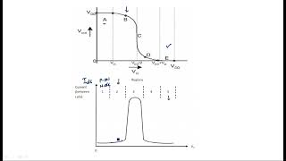
● Subthreshold and Superthreshold Operation: Transistors can operate in subthreshold (low current, low power) or superthreshold (high current, normal operation) regions.
Detailed Explanation
This chunk introduces two operational modes of CMOS transistors: subthreshold and superthreshold. In subthreshold operation, when the gate voltage is below the threshold, a very small current can still flow — this is useful for low-power applications. Conversely, in superthreshold operation, when the voltage exceeds the threshold, the transistor conducts a significant amount of current, allowing normal operation in most digital circuits. Understanding these modes helps designers optimize power consumption for specific applications.
Examples & Analogies
Think of a battery. When you barely press the power button (subthreshold), it can still power a small light, showing it works at a low level. When you press it harder (superthreshold), the light shines brightly, utilizing the full power of the battery. This is akin to how transistors can operate efficiently at low power or at full strength depending on the applied voltage.
Threshold Voltage
Chapter 5 of 5
🔒 Unlock Audio Chapter
Sign up and enroll to access the full audio experience
Chapter Content
● Threshold Voltage: The voltage at which a MOSFET turns on. Variations in Vth can occur due to process, temperature, and biasing effects.
Detailed Explanation
The threshold voltage (Vth) is a critical parameter that dictates when a MOSFET turns on (conducts) or turns off (non-conducting). Factors like manufacturing variations (process), changes in temperature, and the voltage applied to the substrate can alter this threshold. Understanding these variations is essential for reliably designing circuits, as they can affect performance and stability.
Examples & Analogies
Consider a faucet that releases water when you turn it to a certain angle (the threshold of turning). If the faucet is damaged (process variations), the amount of water released changes with temperature (like varying thresholds) and how far you turn the handle (biasing effects). Just as you need to know these factors to control the water flow, engineers must understand Vth to ensure proper functionality in circuit designs.
Key Concepts
-
NMOS and PMOS Transistors: NMOS turns on with VGS > Vth; PMOS turns on with VGS < Vth.
-
CMOS Inverter: Utilizes NMOS and PMOS transistors to invert input signals efficiently.
-
Channel-Length Modulation: Adjusts effective channel length based on drain-source voltage.
-
Subthreshold and Superthreshold Operation: Indicates low current flow below threshold and normal operation above it.
-
Threshold Voltage: Critical point determining when a MOSFET can conduct, subject to variations.
Examples & Applications
An NMOS transistor conducting when its gate voltage exceeds 2V, while a PMOS turns on when gate voltage is below -2V.
In a CMOS inverter, if the input voltage is 5V, the output will be 0V due to NMOS turning on and PMOS turning off.
Memory Aids
Interactive tools to help you remember key concepts
Rhymes
NMOS is a gate that must rise, PMOS turns on when the gate’s in disguise.
Stories
Imagine two friends, NMOS and PMOS, who only play at different gates of voltage. NMOS loves to play when the voltage is high, but PMOS is happier when the voltage is low. Together, they create the perfect balance of power in circuits!
Memory Tools
Think of the word 'GATE' - 'G' for Gate, needing to exceed for NMOS, and 'A' for Always less than the threshold for PMOS.
Acronyms
For remembering operation modes
'SASS' for Subthreshold
Active
Saturation
Superthreshold.
Flash Cards
Glossary
- NMOS
A type of MOSFET that conducts when the gate-source voltage is above the threshold voltage.
- PMOS
A type of MOSFET that conducts when the gate-source voltage is below the threshold voltage.
- Threshold Voltage (Vth)
The minimum gate voltage required to create a conductive channel in a MOSFET.
- ChannelLength Modulation
The effect observed in MOSFETs where the effective length of the channel changes with the drain-source voltage.
- Subthreshold Operation
MOSFET operation below the threshold voltage, where a small current still flows.
- Superthreshold Operation
MOSFET operation above the threshold voltage, allowing normal operation and significant current flow.
Reference links
Supplementary resources to enhance your learning experience.