
Fault Models in Electronic Systems
Enroll to start learning
You’ve not yet enrolled in this course. Please enroll for free to listen to audio lessons, classroom podcasts and take practice test.
Interactive Audio Lesson
Listen to a student-teacher conversation explaining the topic in a relatable way.
Introduction to Fault Models
🔒 Unlock Audio Lesson
Sign up and enroll to listen to this audio lesson

Today, we will explore fault models in electronic systems. Can anyone tell me what a fault model is?

Is it something that describes what could go wrong in a circuit?
Exactly! A fault model provides a blueprint for understanding errors in circuits. It helps us in designing tests. To remember, think of the acronym 'FAME' — Faults Are Modelled Explicitly.

So, are there different types of faults?
Yes! Let’s discuss the main types of fault models.
Types of Fault Models
🔒 Unlock Audio Lesson
Sign up and enroll to listen to this audio lesson

The first type is 'Stuck-At Faults'. Does anyone know what that means?

That's when a signal is stuck at a fixed logic level?
Correct! This is the simplest and most common type. What about 'Bridging Faults'?

That's when two lines accidentally connect, right?
Correct! Bridging faults lead to incorrect propagation of signals. Remember, use the mnemonic 'BBSD' — 'Bridging Brings Signal Deceit'.
What are 'Delay Faults'?
These occur when a signal takes too long to propagate. It's crucial in high-speed circuits.
Open and Inductive Faults
🔒 Unlock Audio Lesson
Sign up and enroll to listen to this audio lesson
'Open Circuit Faults' occur when connections aren’t made properly. Can anyone think of an example?
Maybe broken wires?
Exactly! Lastly, we have 'Inductive and Capacitive Faults'. Why are they significant?
Because they can lead to unpredictable behavior?
Precisely! These faults result from electromagnetic interference and are tough to detect. Use the memory aid 'Chameleon' — these faults blend in and are hard to spot!
Fault Simulation
🔒 Unlock Audio Lesson
Sign up and enroll to listen to this audio lesson
Now that we know about different faults, let’s discuss 'Fault Simulation'. Why is it important?
To test if our designs can detect faults?
Exactly! And 'Fault Coverage' tells us how many faults our tests can detect. What do you think it indicates about test quality?
Higher coverage means better tests?
Correct! A comprehensive test suite leads to higher reliability. Always remember, more coverage means more confidence in the system!
Introduction & Overview
Read summaries of the section's main ideas at different levels of detail.
Quick Overview
Standard
Fault models are essential for understanding potential failures in electronic systems. This section explores various types of fault models, including stuck-at faults, bridging faults, and delay faults, as well as emphasizes the significance of fault simulation and fault coverage in testing methodologies.
Detailed
Fault Models in Electronic Systems
This section provides an overview of fault models which describe the various types of failures or defects that can occur within electronic systems or circuits. A fault model functions as a blueprint for developing test patterns and identifying defects effectively. Understanding the types of fault models is crucial for designing robust systems that can withstand errors.
Types of Fault Models
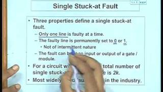
- Stuck-At Faults: The most common model where a signal line is permanently set to either high (1) or low (0), regardless of the inputs due to issues like manufacturing defects.
- Bridging Faults: Occur when two or more signal lines are unintentionally connected, causing incorrect signals to propagate through the circuit.
- Delay Faults: Happen when there’s a delay in signal propagation which may lead to timing problems, particularly in high-speed circuits.
- Transition Faults: Involve failure in signal transitions between logic states, typically due to timing issues or gate behavior problems.
- Open Circuit Faults: Result from disconnected parts of the circuit, often due to manufacturing errors like broken traces.
- Inductive and Capacitive Faults: Arise from electromagnetic effects and can cause unpredictable behavior, being hard to detect with regular testing methods.
Fault Simulation and Fault Coverage
Fault simulation is the method used to check if generated test patterns can reveal various faults in a circuit. Fault coverage indicates the proportion of faults detected by the test suite: higher coverage means more effective testing and higher reliability of the circuit.
Youtube Videos


Audio Book
Dive deep into the subject with an immersive audiobook experience.
Overview of Fault Models
Chapter 1 of 2
🔒 Unlock Audio Chapter
Sign up and enroll to access the full audio experience
Chapter Content
A fault model describes the types of failures or defects that can occur within a system or circuit. It serves as a blueprint for developing test patterns and strategies that can identify these defects. Different types of faults are modeled to reflect different failure mechanisms in electronic circuits.
Detailed Explanation
A fault model is an abstract representation that outlines various ways a circuit can fail. These models help engineers create tests that can reveal these faults during a circuit's operation. By understanding the potential faults, engineers can anticipate problems and design tests that are specifically aimed at detecting these failures, thus enhancing the reliability of electronic systems.
Examples & Analogies
Think of a fault model like a doctor's diagnosis chart. Just as a doctor identifies possible illnesses based on symptoms, engineers use fault models to identify potential failures in a circuit. By diagnosing the types of faults that could occur, engineers can better prepare to test and treat the electronics, ensuring they function correctly.
Types of Fault Models
Chapter 2 of 2
🔒 Unlock Audio Chapter
Sign up and enroll to access the full audio experience
Chapter Content
3.2.1 Types of Fault Models
- Stuck-At Faults: This is the simplest and most commonly used fault model in digital circuits. A stuck-at fault occurs when a signal line or node in the circuit is 'stuck' at a fixed value, either logic high (1) or logic low (0), regardless of the expected input.
- Bridging Faults: A bridging fault occurs when two or more signal lines in a circuit are unintentionally connected due to a short or manufacturing defect.
- Delay Faults: Delay faults occur when a signal takes longer to propagate through the circuit than expected.
- Transition Faults: These faults arise when a signal does not transition from one logic state to another as expected.
- Open Circuit Faults: An open circuit fault occurs when a connection or wire is not made properly.
- Inductive and Capacitive Faults: These faults arise from parasitic effects, such as inductive coupling or capacitive coupling between traces or components.
Detailed Explanation
There are several types of fault models, each representing a different kind of failure mechanism in electronic circuits.
- Stuck-At Faults: Imagine a light switch that won't turn off; it stays on regardless of your attempts to flip it. This kind of fault represents a line in the circuit that cannot change states.
- Bridging Faults: Think of this as two roads merging unexpectedly, which causes traffic problems. When lines unintentionally connect, they can pass incorrect signals.
- Delay Faults: These represent delays in signal transmission, akin to a slow delivery service causing missed appointments.
- Transition Faults: Imagine a traffic light that fails to change colors. This can lead to confusion and accidents, similar to signals not properly transitioning in a circuit.
- Open Circuit Faults: This is like a broken link in a chain; the connection is severed, leading to a disrupted flow.
- Inductive and Capacitive Faults: These are challenging to detect, like finding an invisible wire that interferes with your Wi-Fi signal. They can cause unpredictable circuit behavior.
Examples & Analogies
Consider a team trying to score in a soccer game:
- If one player can never move past a certain point (like a stuck-at fault), it limits the team's options.
- If two players inadvertently tackle each other (bridging fault), they can't advance the ball properly.
- If a player takes too long to respond to a pass (delay fault), they may miss scoring opportunities.
- If a player forgets to switch positions when the play changes (transition fault), it can confuse the team's strategy.
- If a player is absent from the field (open circuit fault), the formation falls apart.
- Finally, if the referee enforces strange new rules (inductive and capacitive faults), it can disrupt the entire game.
Key Concepts
-
Fault Models: Essential frameworks for understanding types of failures in circuits.
-
Types of Faults: Different fault models serve different types of malfunction scenarios.
-
Fault Simulation: The process to test whether faults can be detected by test patterns.
-
Fault Coverage: The effectiveness of tests as indicated by the percentage of detected faults.
Examples & Applications
A stuck-at fault might be caused by a manufacturing defect leading a signal to always read as high.
Delay faults can significantly affect a high-speed processor, potentially causing it to miss critical timing signals.
Memory Aids
Interactive tools to help you remember key concepts
Rhymes
When signals are stuck and can't relay, remember the fault is here to stay.
Stories
Imagine a busy post office. The stuck-at fault is like a mailman who only delivers letters to one address and ignores all others.
Memory Tools
Use 'BDSOC' to remember Bridging, Delay, Stuck-At, Open Circuit faults.
Acronyms
Remember 'FAME' — Faults Are Modelled Explicitly to recall the purpose of fault models.
Flash Cards
Glossary
- Fault Model
A framework describing the types of failures that can occur in a system or circuit.
- StuckAt Fault
A fault where a signal is fixed at a logic level regardless of input.
- Bridging Fault
Occurs when two signal lines are unintentionally connected.
- Delay Fault
A condition where a signal takes longer than expected to propagate.
- Transition Fault
When a signal fails to transition between logic states as expected.
- Open Circuit Fault
Describes a disconnection in a circuit, causing parts to be inactive.
- Inductive Fault
Faults from inductive coupling which can cause erratic circuit behavior.
- Capacitive Fault
Faults arising from capacitive coupling between components.
- Fault Simulation
The process of simulating faults in a system to verify detection capabilities.
- Fault Coverage
The percentage of faults a test suite can detect.
Reference links
Supplementary resources to enhance your learning experience.