
Types of Fault Models
Enroll to start learning
You’ve not yet enrolled in this course. Please enroll for free to listen to audio lessons, classroom podcasts and take practice test.
Interactive Audio Lesson
Listen to a student-teacher conversation explaining the topic in a relatable way.
Understanding Stuck-At Faults
🔒 Unlock Audio Lesson
Sign up and enroll to listen to this audio lesson

Let's begin with stuck-at faults, which are the simplest and most prevalent issues in digital circuits. A signal can be stuck high or low, which means it doesn’t respond to inputs. Can anyone explain why this fault might occur?

Maybe it’s due to manufacturing defects or wear over time?
Exactly! They can be caused by things like faulty connections or aging components. Remember, a simple way to visualize this is to think of a stuck faucet – it just won’t let the water flow even if you turn the tap!

So, how do we test for these faults?
Great question! We create tests that check if a line is consistently high or low. Implementing effective test patterns is key to identifying these faults in production.
Exploring Bridging Faults
🔒 Unlock Audio Lesson
Sign up and enroll to listen to this audio lesson

Moving on to bridging faults, which happen when two signal lines unintentionally connect. Can someone think of a real-world analogy for this?

It’s like two wires touching each other by mistake, right?
Exactly! This connection can cause incorrect signals to propagate. What might happen if we don’t detect these faults?

The system could malfunction or produce wrong outputs!
Correct! Testing for bridging faults requires specific patterns that can reveal these unexpected connections. Let’s keep this analogy in mind as we progress.
Understanding Delay and Transition Faults
🔒 Unlock Audio Lesson
Sign up and enroll to listen to this audio lesson
Let’s now examine delay faults. These occur when a signal takes longer to propagate than expected, especially in high-speed circuits. What implications does this have for performance?
If the signal delays, it might cause timing violations, right?
Exactly! And even a minor delay can disrupt the entire system's operation. Transition faults are somewhat similar but focus on whether the signals transition between states as expected. Why do you think this is particularly crucial?
Because it can affect the operation of logic gates and timing in circuits?
Well said! Precise transitions are vital for maintaining signal integrity. When testing these faults, we identify potential timing issues that could lead to functional failures.
Investigation of Open Circuit Faults
🔒 Unlock Audio Lesson
Sign up and enroll to listen to this audio lesson
Next, let's discuss open circuit faults, which are essentially broken connections that can lead to disconnected sections of a circuit. Can anyone share an example of how this might happen?
Like when there’s a broken wire or bad solder joint?
Exactly! These faults can lead to parts of a circuit being entirely inactive. Testing for open circuit faults involves checking the continuity of connections. What might we miss if we overlook this type of fault?
We might not realize a part of the circuit isn’t functioning at all!
Correct! Thorough testing helps ensure that every connection is proper, maintaining the reliability of the system.
Inductive and Capacitive Faults
🔒 Unlock Audio Lesson
Sign up and enroll to listen to this audio lesson
Lastly, let’s look at inductive and capacitive faults. These arise from parasitic effects and can cause unpredictable behavior. Why might they be particularly tricky to detect?
Because they might not show up in standard testing methods?
Exactly! They can lead to issues like crosstalk between lines. Engineers often need specialized techniques to uncover these faults. Remember, adapting our testing strategies is key to effectively addressing all fault types.
So, a mix of knowledge and creativity in testing is necessary!
Yes! A diverse approach is crucial for maximizing fault coverage in our systems. Excellent insights today, everyone!
Introduction & Overview
Read summaries of the section's main ideas at different levels of detail.
Quick Overview
Standard
The section discusses various fault models, including stuck-at faults, bridging faults, delay faults, transition faults, open circuit faults, and inductive/capacitive faults. Each model is crucial for developing effective test patterns to ensure reliable electronic systems.
Detailed
Types of Fault Models
Electronic systems can experience various types of faults that compromise their functionality. This section introduces several fault models used in digital circuits, elaborating on their characteristics and implications for testing. Understanding these fault models is vital in creating efficient testing methodologies that can effectively identify defects within systems. Here, we cover:
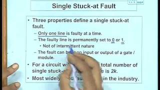
- Stuck-At Faults: The most common type of fault, where a signal line is fixed at either logic high (1) or logic low (0), causing it to ignore input signals. This can arise from manufacturing defects or aging.
- Bridging Faults: Occur when two or more signal lines are unintentionally connected, leading to incorrect signal propagation.
- Delay Faults: Involve signals taking longer than expected to propagate, which can create timing issues in high-speed circuits.
- Transition Faults: Happen when a signal fails to transition between states properly, which is critical in high-speed digital operations.
- Open Circuit Faults: Result from broken connections or improperly soldered components, causing disconnections in the circuit.
- Inductive and Capacitive Faults: Stem from parasitic effects leading to unpredictable circuit behavior, making them challenging to detect with regular testing methods.
Together, these models form the basis for diagnosing issues in electronic systems and crafting robust testing strategies.
Youtube Videos


Audio Book
Dive deep into the subject with an immersive audiobook experience.
Stuck-At Faults
Chapter 1 of 6
🔒 Unlock Audio Chapter
Sign up and enroll to access the full audio experience
Chapter Content
● Stuck-At Faults: This is the simplest and most commonly used fault model in digital circuits. A stuck-at fault occurs when a signal line or node in the circuit is “stuck” at a fixed value, either logic high (1) or logic low (0), regardless of the expected input. These faults can be caused by physical defects like manufacturing issues or aging.
Detailed Explanation
Stuck-at faults are a basic type of defect in digital circuits where a specific wire or node is unable to change its state. For instance, if a wire is supposed to toggle between high (1) and low (0), but it remains at 1 regardless of the input, that is a stuck-at fault. Such faults can occur due to manufacturing flaws or the aging of materials. In testing, detecting a stuck-at fault is critical because these errors can lead to incorrect operation of the circuit, meaning it will not perform as intended.
Examples & Analogies
Think of a light switch in your home that is broken and can no longer be turned off. No matter how many times you flip the switch, the light remains on. This is similar to a stuck-at fault where a circuit element cannot change state, leading to a failure in its overall function.
Bridging Faults
Chapter 2 of 6
🔒 Unlock Audio Chapter
Sign up and enroll to access the full audio experience
Chapter Content
● Bridging Faults: A bridging fault occurs when two or more signal lines in a circuit are unintentionally connected due to a short or manufacturing defect. This causes an incorrect voltage or logic state to be propagated through the circuit.
Detailed Explanation
Bridging faults happen when two different wires that are not supposed to connect inadvertently do so. This can happen because of issues during the manufacturing process, like a stray soldering point causing a short circuit. When this occurs, the signals meant for different paths might interfere with each other, leading to unexpected behavior in the circuit. For example, if a line that sends a logic high signal accidentally connects to a line meant to send a logic low signal, the circuit could become confused about the true state of its inputs.
Examples & Analogies
Imagine two roads (signal lines) that are supposed to be separate but have a construction error that merges them into one. Vehicles (signals) intended for different destinations now intermingle, causing traffic issues (wrong logic states) and confusion about where each should go.
Delay Faults
Chapter 3 of 6
🔒 Unlock Audio Chapter
Sign up and enroll to access the full audio experience
Chapter Content
● Delay Faults: Delay faults occur when a signal takes longer to propagate through the circuit than expected. These faults can lead to timing violations, especially in high-speed circuits, affecting system performance.
Detailed Explanation
Delay faults are significant in high-frequency circuits where timing is crucial. A signal that should quickly change from low to high might experience unexpected delays due to factors such as component inefficiencies or longer than anticipated travel distances. If signals do not arrive at their destination at the correct time, it can lead to logic errors, as the system may make decisions based on outdated information, leading to malfunctions.
Examples & Analogies
Consider a relay race where runners must pass a baton within a specific time frame. If one runner is too slow in passing the baton (the signal), the next runner may start running before they have the baton, leading to confusion and mistakes. This situation mirrors how delay faults can disrupt the expected timing in digital circuits.
Transition Faults
Chapter 4 of 6
🔒 Unlock Audio Chapter
Sign up and enroll to access the full audio experience
Chapter Content
● Transition Faults: These faults arise when a signal does not transition from one logic state to another as expected, often due to improper gate behavior or timing issues. Transition faults are important in high-speed digital circuits where precise signal transitions are crucial.
Detailed Explanation
Transition faults occur when signals between logic states (like from 0 to 1) don't switch correctly. This might happen due to malfunctioning components in a circuit, leading to situations where the circuit expects a different state than what it receives. In fast-paced circuits, such failures can disrupt operations because they rely on quick transitions to maintain performance, resulting in potential data processing failures.
Examples & Analogies
Think of a traffic light that is supposed to change from red to green at a specific time. If it gets stuck and doesn’t change when it’s supposed to (transition fault), cars running on green (circuits relying on the signal) might enter an intersection too soon, causing traffic accidents (system failures).
Open Circuit Faults
Chapter 5 of 6
🔒 Unlock Audio Chapter
Sign up and enroll to access the full audio experience
Chapter Content
● Open Circuit Faults: An open circuit fault occurs when a connection or wire is not made properly, causing a part of the circuit to be disconnected. This can occur due to broken traces or poor soldering during manufacturing.
Detailed Explanation
An open circuit fault happens when a part of the circuit is not connected as intended, which can render parts of the circuit inoperative. This situation can emerge from manufacturing mistakes, such as a broken wire or a poor solder connection. Essentially, if the circuit cannot close, it cannot function properly, leading to operational failures.
Examples & Analogies
Imagine trying to send a message by creating a chain of people passing it along. If one person (connection) doesn't link into the chain or leaves the group, the message fails to reach the last person (the end of the circuit), similar to how open circuit faults interrupt the flow in electronic systems.
Inductive and Capacitive Faults
Chapter 6 of 6
🔒 Unlock Audio Chapter
Sign up and enroll to access the full audio experience
Chapter Content
● Inductive and Capacitive Faults: These faults arise from parasitic effects, such as inductive coupling or capacitive coupling between traces or components. They often lead to unpredictable behavior and are difficult to detect using conventional testing methods.
Detailed Explanation
Inductive and capacitive faults result from unintended electrical interactions between various elements in a circuit. Inductive coupling occurs when a changing current in one wire induces a voltage in another nearby wire, while capacitive coupling involves charge transfer between closely spaced components. These interactions can create noise and unpredictable behaviors in signals, making them hard to diagnose with standard tests because they mimic normal operations.
Examples & Analogies
Think of two radios placed too close together. If one starts picking up interference from the other, it can distort the music being transmitted. This is akin to inductive and capacitive faults, where signals interfere with one another, leading to unexpected circuit behavior and challenges in troubleshooting.
Key Concepts
-
Stuck-At Faults: A primary fault model in which a signal remains fixed at a logical level, resulting in consistent output regardless of intended input.
-
Bridging Faults: Faults resulting from unintended electrical connections between signal lines, causing erroneous outputs.
-
Delay Faults: Faults characterized by slower than expected signal propagation through the circuit, leading to timing violations.
-
Transition Faults: Issues that occur when signals do not transition correctly between states, which can disrupt digital operations.
-
Open Circuit Faults: Faults that arise from broken connections, preventing signals from reaching their intended destinations.
-
Inductive and Capacitive Faults: Complex errors originating from capacitive or inductive effects that can introduce unpredictable behaviors.
Examples & Applications
A stuck-at fault may occur in a circuit where a wire supposed to switch between 0 and 1 remains stuck at 0, leading to a failure in performing logical operations.
A bridging fault could occur in a PCB where two adjacent pins short together, causing a logic high signal to appear where a logic low is expected.
Memory Aids
Interactive tools to help you remember key concepts
Rhymes
When signals are stuck, they can't play, they won't change no matter the way.
Stories
Imagine a busy highway with cars that are stuck at a traffic signal. No matter how much the light changes, some cars just won’t move. This is like a stuck-at fault where the circuit can't change its signal.
Memory Tools
SBC, DTC, OC - Stuck, Bridging, Capacitive, Delay, Transition, Open Circuit; remember these to avoid a fault desert!
Acronyms
FAM BDO - Faults
Stuck-At (F)
Bridging (B)
Delay (D)
Transition (T)
Open Circuit (O) - remember FAM BDO to cover faults!
Flash Cards
Glossary
- StuckAt Faults
When a signal line is stuck at a fixed value (1 or 0), not responding to input changes.
- Bridging Faults
Occur when two or more signal lines unintentionally connect, causing incorrect signal propagation.
- Delay Faults
Faults caused by a signal taking longer to propagate through a circuit than expected.
- Transition Faults
Happen when a signal fails to transition correctly between logic states.
- Open Circuit Faults
Faults that occur when there is a break in a connection, leading to disconnection in the circuit.
- Inductive Faults
Faults arising from inductive coupling, causing unexpected interactions between circuit elements.
- Capacitive Faults
Faults stemming from capacitive coupling, leading to erratic circuit behavior.
Reference links
Supplementary resources to enhance your learning experience.