
Comparison: Planar MOSFET vs FinFET
Interactive Audio Lesson
Listen to a student-teacher conversation explaining the topic in a relatable way.
Fundamental Differences in Structure
🔒 Unlock Audio Lesson
Sign up and enroll to listen to this audio lesson

Today, we're comparing two types of transistors: Planar MOSFETs and FinFETs. Can anyone tell me what the main structural difference is between these two?

I think Planar MOSFETs are flat, while FinFETs have a 3D shape?
Exactly! Planar MOSFETs are indeed 2D, while FinFETs have a fin-like structure that rises vertically. This 3D aspect gives FinFETs better control over the current flow. We can remember this with the acronym '3D-Gate' for FinFET, highlighting its multiple-dimensional control!

What does having a 3D structure help with exactly?
Great question! The 3D structure allows for better electrostatic control, which is crucial as we scale down to smaller nodes. This leads to improved performance in devices.

So, is it true that FinFETs are better as we go below 22nm in technology?
Yes! FinFETs were designed specifically to tackle the shortcomings of Planar MOSFETs at smaller scales. Great observation!
To wrap up, the transition from 2D to 3D can be remembered with the mnemonic: '3D means more control,' highlighting the advantage of FinFETs.
Comparison of Gate Control
🔒 Unlock Audio Lesson
Sign up and enroll to listen to this audio lesson

Now let's dive into gate control. How does the number of gates impact transistor performance?

More gates mean more control over the channel, right?
Exactly! FinFETs utilize triple gates surrounding the fin, which dramatically improves control over the channel compared to the single gate of Planar MOSFETs. This aids in reducing short-channel effects, which are quite problematic at small nodes. Remember, 'Triple Gate, Triple Control' for FinFETs!
What are short-channel effects?
Short-channel effects occur as the channel length decreases and can lead to leakage and performance issues. FinFETs mitigate these issues effectively. Can anyone think of why these effects are such a problem?
I guess because it could cause a transistor to not switch properly?
Correct! That can lead to higher power consumption and reduced performance. So, always remember that the channel's control is vital for efficient transistor operation.
Leakage Current Comparison
🔒 Unlock Audio Lesson
Sign up and enroll to listen to this audio lesson
Next up, let’s discuss leakage current. What do we know about it regarding Planar MOSFETs versus FinFETs?
I remember that Planar MOSFETs have high leakage current.
That's right! Planar MOSFETs tend to have high leakage due to thin gate oxides, while FinFETs have more effective gate control and lower leakage currents. Who can explain why fin structures help with this?
It's because the gate wraps around more sides of the channel!
Exactly! The fin structure allows the gate to control the channel from multiple angles, reducing leakage. Think of it like wrapping a present tightly compared to just placing a cover on it. Thus, 'Wrap It Tight, Leak Less'!
So, FinFETs are way better in power-saving applications?
You got it! Lower leakage correlates to higher efficiency in devices. FinFETs provide a significant advantage, particularly in low-power applications.
Introduction & Overview
Read summaries of the section's main ideas at different levels of detail.
Quick Overview
Standard
The comparison between Planar MOSFETs and FinFETs reveals significant advancements made with FinFET technology. FinFETs, characterized by their 3D structure and superior gate control, address the limitations of Planar MOSFETs, particularly at smaller technology nodes, leading to reduced leakage currents and better power efficiency.
Detailed
Comparison: Planar MOSFET vs FinFET
In the transition from traditional planar MOSFETs to FinFETs, several key differences emerge:
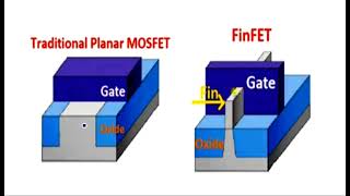
- Structure: Planar MOSFETs maintain a 2D planar structure, while FinFETs utilize a 3D fin-based channel that significantly enhances control over the device.
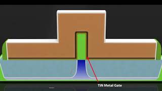
- Gate Control: Planar MOSFETs feature a single gate configuration, whereas FinFETs possess a triple gate setup (top and sides), providing improved electrostatic control over the channel.
- Short-Channel Effects (SCE): Planar MOSFETs struggle with SCE at smaller technology nodes, leading to performance issues. Conversely, FinFETs excel in controlling these effects, making them suitable for advanced nodes.
- Leakage Current: The leakage current in Planar MOSFETs is considerably higher due to their design limitations. FinFETs mitigate this with their 3D structure, resulting in lower leakage currents.
- Power Efficiency: FinFET technology dramatically enhances power efficiency, allowing for lower operating voltages and reduced power consumption.
Overall, while Planar MOSFETs are simpler to fabricate, FinFETs offer substantial advantages in performance and scalability, marking a pivotal innovation in semiconductor technology.
Youtube Videos


Audio Book
Dive deep into the subject with an immersive audiobook experience.
Structural Differences
Chapter 1 of 6
🔒 Unlock Audio Chapter
Sign up and enroll to access the full audio experience
Chapter Content
Feature
Planar MOSFET
FinFET
Structure
2D planar
3D fin-based
Detailed Explanation
In this chunk, we compare the structural design of Planar MOSFETs and FinFETs. A Planar MOSFET has a two-dimensional structure, meaning it's flat and laid out on a surface. In contrast, a FinFET has a three-dimensional design where the channel is raised like fins, allowing for better use of space and electrical characteristics.
Examples & Analogies
Think of a Planar MOSFET like a flat pancake, which spreads out on a plate, while a FinFET is like a stack of books—the books are arranged upright and take advantage of vertical space, allowing for more options in how we manage them.
Gate Control Mechanisms
Chapter 2 of 6
🔒 Unlock Audio Chapter
Sign up and enroll to access the full audio experience
Chapter Content
Gate Control
Single gate
Triple gate (top and sides)
Detailed Explanation
This chunk focuses on how the gates operate in each design. A Planar MOSFET has a single gate that controls the channel, whereas a FinFET has three gates that wrap around the fin-shaped channel. This triple-gate structure allows for better control over the flow of electrons, leading to improved performance.
Examples & Analogies
Imagine a single door (the Planar MOSFET) that only opens and closes to let people in and out of a room. Now, picture a room with three doors (the FinFET) on different sides. You can manage who enters or exits much better with multiple doors, providing greater flexibility and control.
Short-Channel Effects (SCE) Control
Chapter 3 of 6
🔒 Unlock Audio Chapter
Sign up and enroll to access the full audio experience
Chapter Content
SCE Control
Poor at small nodes
Excellent
Detailed Explanation
Short-channel effects refer to issues that arise when the size of the transistor becomes very small, affecting its performance. Planar MOSFETs struggle with these effects at smaller nodes, leading to inefficiency. In contrast, FinFETs are designed to maintain excellent control over these effects even as transistor sizes shrink.
Examples & Analogies
Consider a garden hose. A traditional hose (Planar MOSFET) may struggle to maintain water pressure when it's squished down to a smaller size, while a more robust hose design (FinFET) can handle the pressure better, maintaining a strong flow regardless of its size.
Leakage Current Characteristics
Chapter 4 of 6
🔒 Unlock Audio Chapter
Sign up and enroll to access the full audio experience
Chapter Content
Leakage Current
High
Low
Detailed Explanation
Leakage current is the unwanted current that flows through a transistor when it's supposed to be off. Planar MOSFETs have high leakage currents due to their structure, making them less efficient. FinFETs have much lower leakage currents, which improves overall device performance and energy efficiency.
Examples & Analogies
Think of a leaky faucet (Planar MOSFET) that drips water even when turned off, wasting resources. On the other hand, a well-maintained faucet (FinFET) does not leak when closed, conserving water and improving the efficiency of your plumbing.
Power Efficiency
Chapter 5 of 6
🔒 Unlock Audio Chapter
Sign up and enroll to access the full audio experience
Chapter Content
Power Efficiency
Moderate
High
Detailed Explanation
This chunk addresses how efficiently each type of transistor uses power. Planar MOSFETs generally offer moderate efficiency, which can be improved but not optimized beyond a certain limit. On the other hand, FinFETs are designed for high power efficiency, allowing devices to run better on less power.
Examples & Analogies
Imagine two cars: one (Planar MOSFET) that consumes gas moderately and can run a decent distance on a tank, versus a hybrid car (FinFET) that efficiently uses both gas and electric energy to go much farther on the same amount of fuel.
Fabrication Complexity
Chapter 6 of 6
🔒 Unlock Audio Chapter
Sign up and enroll to access the full audio experience
Chapter Content
Fabrication
Simpler
Complex
Detailed Explanation
The final chunk compares the complexity of the manufacturing processes for each type of transistor. Planar MOSFETs are simpler to fabricate, which has made them the industry standard for many years. In contrast, FinFETs are more complex to produce due to their intricate three-dimensional structure, requiring advanced fabrication techniques.
Examples & Analogies
Consider baking a simple cake (Planar MOSFET), which is straightforward and quick. Now picture a multi-tiered wedding cake (FinFET), which requires precision, different techniques, and takes much longer to complete. The complexity increases with the sophistication of the design.
Key Concepts
-
Structure: FinFETs use a 3D fin structure compared to the 2D structure of Planar MOSFETs, allowing for better control.
-
Gate Control: FinFETs have multiple gates providing enhanced control over the current flow in the transistor.
-
Leakage Current: FinFETs exhibit lower leakage currents compared to Planar MOSFETs, contributing to higher efficiency.
-
Short-channel effects: FinFETs better manage short-channel effects, an important consideration for smaller technology nodes.
Examples & Applications
In applications with technology nodes below 22nm, FinFETs offer significant performance improvements over Planar MOSFETs in terms of power efficiency.
Modern processors, such as Intel's latest chips, utilize FinFET technology for better speed and reduced power consumption.
Memory Aids
Interactive tools to help you remember key concepts
Rhymes
In a fin structure, current flows with grace, / While planar shapes just can't keep pace.
Stories
Imagine a fisherman, using a net (FinFET) that captures every fish (current) perfectly, contrasted with a flat pan (Planar MOSFET), where many fish slip away.
Memory Tools
Remember 'TFPL' - The FinFET has Triple Gates for Power efficiency, while Planar has Less (TFPL).
Acronyms
'3DGCC' - 3D Gate Control and Competence, representing FinFET's design.
Flash Cards
Glossary
- Planar MOSFET
A traditional type of metal-oxide-semiconductor field-effect transistor (MOSFET) characterized by a flat, 2D structure.
- FinFET
A type of 3D transistor that has a fin-shaped channel structure, allowing for improved control and performance.
- Gate Control
The ability of a transistor's gate(s) to control the flow of current through the channel.
- ShortChannel Effects (SCE)
Phenomena that occur in devices when the channel length is smaller than the Debye length, leading to inefficiencies.
- Leakage Current
The small amount of current that flows through a device when it is supposed to be off, often increased in traditional MOSFETs.
Reference links
Supplementary resources to enhance your learning experience.