
Head Loss (Darcy Weisbach Equation)
Enroll to start learning
You’ve not yet enrolled in this course. Please enroll for free to listen to audio lessons, classroom podcasts and take practice test.
Interactive Audio Lesson
Listen to a student-teacher conversation explaining the topic in a relatable way.
Major Pipe Head Loss
🔒 Unlock Audio Lesson
Sign up and enroll to listen to this audio lesson

Today, we'll explore head losses in fluid systems, starting with major pipe head loss caused by friction. Does anyone remember the Darcy Weisbach equation?

Is it related to how much energy is lost due to the friction in the pipes?
Exactly! The equation is: $h_f = f \frac{L}{D} \frac{V^2}{2g}$. Here, $h_f$ represents the head loss due to friction. Can anyone tell me what the variables $L$, $D$, and $f$ signify?

$L$ is the length of the pipe, $D$ is the diameter, and $f$ is the friction factor.
Correct! So, if we increase the length of the pipe while keeping the diameter constant, what happens to the head loss?

It would increase because the head loss is directly proportional to the length, right?
Absolutely! Great connection. Remember, for friction factors, you often need to reference tables or use empirical correlations. Let's recap: major losses occur from friction, represented by the Darcy equation.
Minor Head Losses
🔒 Unlock Audio Lesson
Sign up and enroll to listen to this audio lesson

Now, let's turn our attention to minor losses in systems: What are some examples of minor losses we might encounter?
Bend losses and things like the loss from valves?
Exactly! We also consider entry and exit losses, although sometimes we may exclude those in our calculations for simplicity. Minor losses can be expressed as $h_{minor} = K \frac{V^2}{2g}$. Who can remind me what $K$ stands for?

$K$ is the sum of loss coefficients from all components!
Right! Good job. Each component, like bends or valves, has specific K values. We combine those to determine the overall minor loss.
Application of Equations
🔒 Unlock Audio Lesson
Sign up and enroll to listen to this audio lesson
Let's apply our knowledge. Suppose we have a pipe connecting two reservoirs, with known lengths and a diameter. Can someone summarize how we would compute head loss?
First, we need to calculate the major head loss using the Darcy equation, then consider any minor losses from components like bends.
Very good! If we have values for all parameters, how would you find the flow rate into a different reservoir?
We would apply Bernoulli's equation, using the computed head losses to find the resultant pressure or velocity.
Excellent! You’ll often see this process described step-wise: compute losses, apply Bernoulli, and find discharge rates.
Introduction & Overview
Read summaries of the section's main ideas at different levels of detail.
Quick Overview
Standard
The section details the calculation of head losses within a fluid system, emphasizing the use of the Darcy Weisbach equation for quantifying major losses due to friction and minor losses due to factors like bends and valves. Various examples illustrate the application of these concepts.
Detailed
Detailed Summary
The Darcy Weisbach equation is crucial for evaluating head loss in fluid systems. This section primarily focuses on two types of head losses:
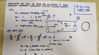
- Major Pipe Head Loss: This is attributed to friction in the pipe, which can be calculated using the Darcy Weisbach equation formulated as:
$$ h_f = f \frac{L}{D} \frac{V^2}{2g} $$
where:
- $h_f$ = head loss due to friction
- $f$ = friction factor
- $L$ = length of the pipe
- $D$ = diameter of the pipe
- $V$ = velocity of fluid
- $g$ = acceleration due to gravity
- Minor Losses: These include various losses that occur in different components of a fluid system, such as:
- Bend losses
- Valve losses
- Entry and exit losses (the latter are excluded in some calculations)
These can be grouped and calculated using loss coefficients associated with each component, often summarized as:
$$ h_{minor} = K \frac{V^2}{2g} $$
where $K$ represents the sum of the loss coefficients for each component.
The section examines the application of these equations with examples involving reservoir systems and calculations of flow rates while considering energy losses across systems.
Youtube Videos


Audio Book
Dive deep into the subject with an immersive audiobook experience.
Understanding Head Loss
Chapter 1 of 4
🔒 Unlock Audio Chapter
Sign up and enroll to access the full audio experience
Chapter Content
So that means I know the head losses that is what is computed here by substituting this value. There will be minor losses like bend losses, valve losses, the entry and exit losses all the components, this entry and exit loss we do not consider it here only the bend loss and valve loss we compute it which we have these values.
Detailed Explanation
Head loss in fluid systems is the reduction in the total mechanical energy of the fluid due to friction and other factors. In this context, the minor losses like those caused by bends and valves are specifically computed. Major head losses, which are often due to pipe friction, are calculated using different equations while minor losses are typically added to the total.
Examples & Analogies
Imagine a garden hose that you’re watering your plants with. If you were to kink the hose (minor loss due to a bend), the water flow decreases, showing how head loss affects water delivery. Also, if you turned on a valve halfway (another minor loss), it further restricts flow, similar to how bends and valves create minor losses in plumbing.
Major Pipe Head Loss Calculation
Chapter 2 of 4
🔒 Unlock Audio Chapter
Sign up and enroll to access the full audio experience
Chapter Content
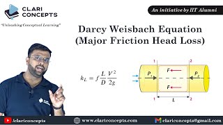
Major pipe head loss (due to friction):
\( h_f = f \frac{L}{D} \frac{V^2}{2g} \)
Where:
- \( h_f \) is the head loss due to friction
- \( f \) is the friction factor
- \( L \) is the length of the pipe
- \( D \) is the diameter of the pipe
- \( V \) is the velocity of fluid
- \( g \) is the acceleration due to gravity
Detailed Explanation
The major head loss due to friction is calculated using the Darcy-Weisbach equation. This equation helps to quantify how much energy is lost, as the fluid travels through a pipe, due to friction against the pipe walls. Each variable in the equation represents an essential factor affecting this loss: friction factors account for the pipe's surface, length and diameter influence how much surface the fluid interacts with, and fluid velocity determines how quickly this interaction occurs.
Examples & Analogies
Think of sliding down a slide at a playground. The longer the slide (analogous to pipe length) and the rougher the surface (akin to the friction factor), the slower you go, just as longer pipes with rough interiors slow down fluid flow more due to friction.
Minor Losses Consideration
Chapter 3 of 4
🔒 Unlock Audio Chapter
Sign up and enroll to access the full audio experience
Chapter Content
Minor losses:
\( h_m = K \frac{V^2}{2g} \)
Where:
- \( K \) is the loss coefficient for minor losses
Detailed Explanation
Minor losses are included in the calculations to account for energy lost due to factors like bends, fittings, and valves in the system. These losses are quantified using a coefficient (K) specific to the type of fitting or valve, and the formula helps to integrate these losses into the overall energy calculations. As with major losses, the result is expressed in terms of head.
Examples & Analogies
If you've ever tried to drink through a straw with holes, you'll notice that the flow becomes weak because of those minor leaks (akin to bends or valves). The loss coefficient helps estimate how much flow is lost due to those leaks.
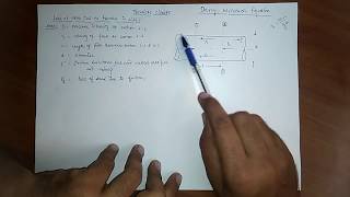
Using Bernoulli’s Equations
Chapter 4 of 4
🔒 Unlock Audio Chapter
Sign up and enroll to access the full audio experience
Chapter Content
Now we are substituting Bernoulli’s equations, the modified Bernoulli’s equations to compute what could be the pressure. So I am not going more detail as you can read this ppt to get these details.
Detailed Explanation
Bernoulli’s equation provides a way to relate pressure, velocity, and height in fluid dynamics. By substituting our loss calculations into Bernoulli’s equation, we can find out how these head losses affect the pressure at various points within the fluid system.
Examples & Analogies
Think of a garden fountain: when you block part of the opening (like losses in a pipe), the water pressure decreases, altering the fountain's height and spray pattern. Similarly, Bernoulli's equations help show how head losses affect pressure and flow rate in a schedule.
Key Concepts
-
Major Losses: Losses due to pipe friction in flow.
-
Minor Losses: Losses attributed to bends, valves, and other fittings in a fluid system.
-
Friction Factor: A dimensionless number that represents the resistance of a pipe to flow.
-
Bernoulli's Equation: An equation that relates pressure, velocity, and elevation in a flowing fluid.
Examples & Applications
For a 3000m long and 0.7m diameter pipe with a friction factor of 0.024, the major head loss can be computed using the Darcy Weisbach equation.
To calculate the total energy losses in a pipeline system, combine the major and minor losses, equating this to the elevation differences in connected reservoirs.
Memory Aids
Interactive tools to help you remember key concepts
Rhymes
In pipes we see the fluid flow, Friction takes a toll, you know. Major losses make it slow, Minor too, when bends do show.
Stories
Imagine a water ride where the flow slows down in curves - that's like minor losses in a pipe! And the stretch of the ride represents the major losses.
Memory Tools
For major losses, remember 'FLVD' - Friction, Length, Velocity, Diameter.
Acronyms
Use 'HMP' for head loss
Head
Major (for friction)
and Minor (for components).
Flash Cards
Glossary
- Darcy Weisbach Equation
An equation that relates the head loss due to friction in a pipe to the pipe's length, diameter, and flow velocity.
- Major Losses
Head loss primarily resulting from friction in pipes.
- Minor Losses
Head losses associated with components in a fluid system, such as bends and valves.
- Loss Coefficient (K)
A coefficient used to quantify head losses in terms of minor losses from various components.
Reference links
Supplementary resources to enhance your learning experience.