
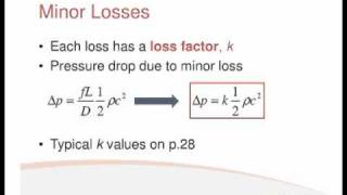
Minor Losses
Enroll to start learning
You’ve not yet enrolled in this course. Please enroll for free to listen to audio lessons, classroom podcasts and take practice test.
Interactive Audio Lesson
Listen to a student-teacher conversation explaining the topic in a relatable way.
Understanding Minor Losses
🔒 Unlock Audio Lesson
Sign up and enroll to listen to this audio lesson

Today, we are diving into the concept of minor losses in fluid systems. Can anyone tell me what minor losses might refer to?

Are they related to losses from pipes and bends?
Exactly! Minor losses occur at fittings, bends, and valves in pipes because they disrupt flow. They can have a considerable impact on total energy loss.

How are these losses calculated?
Good question! We often use equations like the Darcy-Weisbach equation combined with coefficients from Bernoulli’s principle to calculate them.

What are those coefficients for?
The coefficients represent specific loss characteristics of each fitting or valve, essentially quantifying how much energy is lost due to their presence.

Can we see a simple example?
Certainly! If we compute the head loss through a valve with a specific loss coefficient, we can illustrate these concepts more clearly.
Calculating Head Loss
🔒 Unlock Audio Lesson
Sign up and enroll to listen to this audio lesson

Let’s calculate the head loss using the Darcy-Weisbach equation. Who remembers the formula?
It's h_f = f * (L/D) * (V^2/2g).
Correct! In this, 'f' represents the friction factor, 'L' the length, 'D' the diameter, 'V' the velocity, and 'g' the acceleration due to gravity. Let’s plug in some values.
What values should we use?
For instance, let's use a pipe that's 3000 meters long, with a diameter of 0.3 meters, and a friction factor of 0.02. Given a flow velocity of 2 m/s, what’s the head loss?
It appears to be 1.6 meters.
You’re spot on! So, even minor losses contribute significantly to the total loss in a system.
Introduction & Overview
Read summaries of the section's main ideas at different levels of detail.
Quick Overview
Standard
Minor losses in fluid systems occur due to fittings, bends, valves, and other components that affect flow. The section highlights how to calculate these losses using Bernoulli’s equations and the Darcy-Weisbach equation, detailing examples and formulas for practical applications.
Detailed
Detailed Summary
In this section, we explore the concept of minor losses in fluid mechanics, which are significant in understanding total head loss in piping systems. Minor losses arise from various components such as bends, valves, and entrances/exits of pipes that disrupt smooth fluid flow. These losses, although termed 'minor', can be substantial and need accurate computation for efficient system design.
The text guides the reader through the calculation of head loss due to friction and outlines how to incorporate minor losses using Bernoulli’s equation and the Darcy-Weisbach equation. It emphasizes the necessity of recognizing these losses, including those due to specific fittings, to ensure accurate energy loss estimation in fluid systems. Additionally, examples from exams and computational methods are provided to illustrate the practical application of these principles.
Youtube Videos


Audio Book
Dive deep into the subject with an immersive audiobook experience.
Understanding Minor Losses
Chapter 1 of 4
🔒 Unlock Audio Chapter
Sign up and enroll to access the full audio experience
Chapter Content
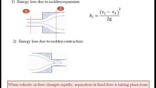
There will be minor losses like bend losses, valve losses, the entry and exit losses. All the components, this entry and exit loss we do not consider it here only the bend loss and valve loss we compute it which we have these values.
Detailed Explanation
Minor losses refer to the energy losses in a fluid system when the fluid encounters obstructions or changes in direction, such as bends in pipes or valves. In this context, the text explains that while entry and exit losses might usually be considered, for the calculations discussed, we are focusing solely on bend losses and valve losses. This simplification can make it easier to calculate the head loss (the loss of pressure in the fluid) during flow.
Examples & Analogies
Imagine water flowing through a garden hose that has a kink (bend) somewhere along its length. When the water tries to flow through this bend, it encounters resistance, causing a drop in pressure or flow speed—this is similar to what happens in pipes with bends or valves.
Calculating Head Loss
Chapter 2 of 4
🔒 Unlock Audio Chapter
Sign up and enroll to access the full audio experience
Chapter Content
Minor losses: \[\Delta h_{minor} = K \frac{V^2}{2g}\]
Detailed Explanation
The formula for minor head losses involves a loss coefficient (K) and the velocity of the fluid (V). The term \(g\) represents the acceleration due to gravity. This equation indicates that head loss (minor losses) increases with the square of the fluid velocity, meaning faster flows will result in greater losses due to bends and valves. This formula allows engineers to quantify how much head (pressure) is lost when the fluid encounters these minor losses during its flow.
Examples & Analogies
Think about riding a bicycle downhill. The faster you go, the more air resistance (analogous to minor losses) you encounter. If the downhill path has sharp turns (like bends in a pipe), you would have to slow down more than on a straight path, losing some of the downhill speed—just like how fluid loses pressure when going through bends and valves.
Modified Bernoulli’s Equation for Minor Losses
Chapter 3 of 4
🔒 Unlock Audio Chapter
Sign up and enroll to access the full audio experience
Chapter Content
Now we are substituting Bernoulli’s equations, the modified Bernoulli’s equations to compute what could be the pressure.
Detailed Explanation
The modified Bernoulli’s equation incorporates both the major and minor losses to provide a more accurate picture of the pressure in the fluid system. This equation accounts for the various forms of energy within the system, including the effects of added losses, which allows engineers to predict the pressure at a given point. It facilitates the understanding of fluid behavior as it flows through different sections of piping, particularly where energy losses occur.
Examples & Analogies
Consider a roller coaster: as it climbs to the top of the hill (gaining potential energy), it will lose some speed as it enters a turn (experiencing an energy loss due to friction and direction change). The same applies to fluids in pipes where energy losses affect pressure and flow.
Applying the Concept to Problem Solving
Chapter 4 of 4
🔒 Unlock Audio Chapter
Sign up and enroll to access the full audio experience
Chapter Content
Physical calculations using Bernoulli's equation involve substituting known values to compute pressures in practical scenarios.
Detailed Explanation
By applying the concepts of minor losses and using the modified Bernoulli's equation, students can solve real-world problems related to fluid mechanics. They can input specific values, such as fluid velocity, pipe length, and loss coefficients, to find pressures at points in their fluid systems. This involves learning how to manipulate the equations based on the scenario presented, which enhances their problem-solving skills.
Examples & Analogies
Much like following a recipe for baking a cake, applying the Bernoulli’s equation requires you to put together various ingredient values (like pressure, velocity, and heights) in order to create a final product (the pressure at a certain point). Just as slight changes in measuring flour or sugar can affect the cake’s outcome, small changes in fluid conditions can significantly affect the pressures in fluid systems.
Key Concepts
-
Minor Losses: Losses due to fittings and bends affecting the fluid flow.
-
Darcy-Weisbach Equation: Equation used to calculate head loss in a pipe system.
-
Bernoulli’s Principle: The principle governing fluid dynamics related to energy conservation.
-
Friction Factor: A coefficient reflecting the resistance to flow in a pipe.
Examples & Applications
Calculating head loss through a valve with a known loss coefficient.
Determining total energy loss in a system considering both major and minor losses.
Memory Aids
Interactive tools to help you remember key concepts
Rhymes
In pipes where bends do weave, minor losses could deceive.
Stories
Imagine a river flowing smoothly until it hits a bend. The water slows down, and some energy is lost, symbolizing minor losses.
Memory Tools
To remember the head loss formula: 'Foolish Little Ducks Perform Very Gracefully'. (Friction factor, Length, Diameter, Velocity, Gravity)
Acronyms
M.L.F.V. - Minor Losses from Fittings and Valves.
Flash Cards
Glossary
- Minor Losses
Small losses of head in fluid flow due to fittings, bends, and other components.
- Friction Factor (f)
A dimensionless factor used to calculate head loss in fluid flow due to friction.
- Bernoulli’s Equation
A principle that describes the conservation of energy in flowing fluids, relating pressure, kinetic energy, and potential energy.
- DarcyWeisbach Equation
An equation used to calculate the head loss due to friction in a pipe.
Reference links
Supplementary resources to enhance your learning experience.