
Total Head Loss Calculations
Enroll to start learning
You’ve not yet enrolled in this course. Please enroll for free to listen to audio lessons, classroom podcasts and take practice test.
Interactive Audio Lesson
Listen to a student-teacher conversation explaining the topic in a relatable way.
Introduction to Head Loss
🔒 Unlock Audio Lesson
Sign up and enroll to listen to this audio lesson

Welcome class! Today, we'll explore head loss in fluid systems. Can anyone tell me what head loss refers to?

Is it the loss of pressure in the fluid?
Exactly! Head loss is the loss of energy due to friction and other factors in a fluid system. There are two types: major and minor losses.

What causes major losses?
Great question! Major losses are primarily due to friction along the pipe's length, which we calculate using the Darcy-Weisbach equation. Repeat it with me: *Darcy-Weisbach*.
Darcy-Weisbach!
Good! We'll dive deeper into these calculations shortly.
Calculating Major Head Loss
🔒 Unlock Audio Lesson
Sign up and enroll to listen to this audio lesson

Now, let’s break down the Darcy-Weisbach equation. Can someone recall the formula?

Remember, it's h_f = f * (L/D) * (V²/2g).
Exactly! And if L is in meters and V in meters per second, the result will give us head loss in meters. If we know the friction factor, length, and diameter, we can quickly calculate head loss.

What about minor losses?
Ah, perfect segue to minor losses! These happen due to fittings like bends or valves. They have their loss coefficients—*write that down*.
Understanding Minor Losses
🔒 Unlock Audio Lesson
Sign up and enroll to listen to this audio lesson
Minor losses can be computed like this: h_m = K * (V²/2g). Who remembers what K stands for?
That's the loss coefficient for the component, right?
Correct! And these coefficients vary based on the type of fitting or valve. Can anyone think of where we might find K values?
Shouldn't they be in reference tables?
Yes! That’s where you can find specific values for different components. Let’s remember K as ‘*K for Knee Joints, elbows, and valves!*’
Application of Bernoulli's Equation
🔒 Unlock Audio Lesson
Sign up and enroll to listen to this audio lesson
Now, let’s apply Bernoulli’s equation to compute pressures at point B using head loss. Who can remind the class what Bernoulli's equation is?
It's basically about energy conservation in fluid flow, right?
Yes! And we modify it to account for head losses. We will soon run through an example that will allow you to master this application.
Are we going to see how to input the values?
Absolutely! Once you know the losses, substituting values into Bernoulli will be your next step.
Real-World Example
🔒 Unlock Audio Lesson
Sign up and enroll to listen to this audio lesson
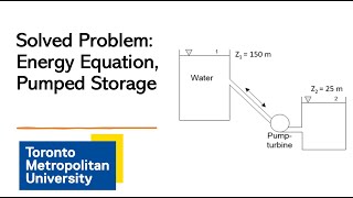
Let’s tackle an example where a pipeline connects two reservoirs 30 meters apart in height. Is anyone ready to calculate the discharge?
Do we have all the required values?
Yes! We’ll use the friction factor and lengths provided to compute head losses and then apply them to solve for Q. Get your calculators ready!
I’ll make a note of the process!
Fantastic! Always remember: Friction leads to lower energy, which we calculate with precision to derive real-world applications.
Introduction & Overview
Read summaries of the section's main ideas at different levels of detail.
Quick Overview
Standard
The section dives into head loss calculations, detailing both major losses due to pipe friction and minor losses attributed to bends, valves, and other fittings. Key equations, including Bernoulli’s principle, are applied through several problem-solving examples to illustrate their significance in real-world applications.
Detailed
Detailed Summary
This section provides a comprehensive look at total head loss calculations, critical in understanding fluid flow and pressure drops in pipelines. Head loss can be categorized into two types: major and minor losses.
Major Head Loss
Major head loss occurs primarily due to friction along the length of a pipe and is computed using the Darcy-Weisbach equation. In fluid mechanics, this equation forms the cornerstone for determining pressure loss caused by friction:
\[ h_f = f \cdot \frac{L}{D} \cdot \frac{V^2}{2g} \]
where:
- \( h_f \) = head loss due to friction
- \( f \) = friction factor
- \( L \) = length of the pipe
- \( D \) = diameter of the pipe
- \( V \) = flow velocity
- \( g \) = acceleration due to gravity
Minor Head Loss
Minor head losses arise from components such as bends, valves, and fittings. These can be calculated by identifying the loss coefficients for each component, applying them in the following formula:
\[ h_m = K \cdot \frac{V^2}{2g} \]
where:
- \( h_m \) = minor head loss
- \( K \) = loss coefficient
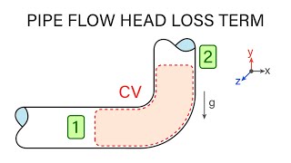
The section illustrates these formulas in practical examples, highlighting the method of substituting values into Bernoulli's equation to compute pressures at specific points in a given system. By solving practical piping problems, learners gain hands-on experience that aids in grasping these concepts thoroughly.
Youtube Videos

![[MAE 242] Pipe flow with major and minor head losses](https://img.youtube.com/vi/WH1fn6dMYiw/mqdefault.jpg)


Audio Book
Dive deep into the subject with an immersive audiobook experience.
Understanding Head Loss
Chapter 1 of 5
🔒 Unlock Audio Chapter
Sign up and enroll to access the full audio experience
Chapter Content
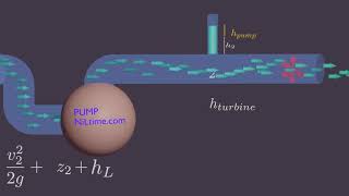
So that means I know the head losses that is what is computed here by substituting this value. There will be minor losses like bend losses, valve losses, the entry and exit losses all the components, this entry and exit loss we do not consider it here only the bend loss and valve loss we compute it which we have these values.
Detailed Explanation
Head loss in a fluid system refers to the loss of pressure due to friction and other factors as the fluid moves through pipes and fittings. In this context, we primarily focus on minor losses, which include bends and valves, as well as the major head loss due to friction. While there are various forms of head loss, not all are considered in every calculation. For example, entry and exit losses are often excluded to simplify the analysis. It emphasizes understanding both major and minor losses in evaluating overall system performance.
Examples & Analogies
Think of it like navigating a twisting path through a forest (the bends and valves represent the twists) where you have to exert more effort to get through compared to walking straight on a clear path (representing the major pipe loss), but sometimes, small obstacles (like entrances/exits) can be ignored for simplification during planning.
Major Pipe Head Loss
Chapter 2 of 5
🔒 Unlock Audio Chapter
Sign up and enroll to access the full audio experience
Chapter Content
Major pipe head loss (due to friction): major_head_loss = (f * (L/D) * (V^2 / 2g)).
Detailed Explanation
Major head loss occurs primarily due to friction as the fluid flows through the pipe. This friction depends on the pipe's length (L), diameter (D), fluid velocity (V), and a friction factor (f), which is determined by the pipe's roughness and flow characteristics. The formula essentially helps calculate how much energy is lost as the fluid overcomes the frictional resistance of the pipe, which is crucial for designing efficient fluid transport systems.
Examples & Analogies
Imagine sliding down a rough slide at a playground. The roughness of the slide causes you to slow down, similar to how friction in a pipe slows down fluid. The longer the slide (the length of the pipe) or the wider the slide (the diameter), will affect how fast you slide down, just like the factors in the major head loss calculation affect fluid flow.
Minor Losses in Systems
Chapter 3 of 5
🔒 Unlock Audio Chapter
Sign up and enroll to access the full audio experience
Chapter Content
Minor losses: minor_loss = (K * (V^2 / 2g)) where K accounts for specific losses due to bends, valves, etc.
Detailed Explanation
Minor losses are additional energy losses that occur due to specific fittings like valves, bends, and other components in a piping system. The value of K varies based on the type of component causing the loss. This equation helps sum up these losses to ensure accurate overall head loss calculations in a piping system, which is important for predicting system behavior effectively.
Examples & Analogies
Consider switching lanes while driving; the turns (bends) you take or the stoplights (valves) you encounter create small interruptions in your speed. Each of these interruptions represents minor losses in our fluid system analogy – they may seem small individually, but together they can significantly affect your travel time and energy used.
Using Bernoulli's Equation
Chapter 4 of 5
🔒 Unlock Audio Chapter
Sign up and enroll to access the full audio experience
Chapter Content
Now we are substituting Bernoulli’s equations, the modified Bernoulli’s equations to compute what could be the pressure.
Detailed Explanation
Bernoulli’s equation relates pressure, velocity, and height in a flowing fluid and allows us to analyze the effects of head loss throughout a system. By understanding how to modify this equation to incorporate losses, we can effectively calculate the pressure at various points in the fluid system. This is integral in engineering applications where predicting pressure conditions is necessary for designing efficient systems.
Examples & Analogies
Imagine a water park ride where the height of the water slide, the speed you go, and the pressure in the water combine to give you a thrilling experience. If the ride had unnecessary bumps or stopped entirely (analogous to losses), your pressure at different points would change, just like how we analyze changes in a fluid system using Bernoulli's principles.
Applying the Concepts to Problems
Chapter 5 of 5
🔒 Unlock Audio Chapter
Sign up and enroll to access the full audio experience
Chapter Content
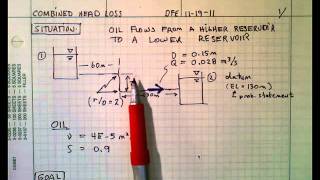
Now you take it the second problems which has the GATE 2015 problems is that the pipe of 0.7 meter diameter has a length of 6 kilometer connects the two reservoirs.
Detailed Explanation
Solving practical problems using the concepts of head loss requires you to identify parameters such as pipe diameter, length, and the elevation difference between reservoirs. This specific example underscores the importance of understanding total energy loss while analyzing fluid flow through a pipeline connecting different points. Analyzing such problems helps in designing systems that are efficient and utilize the least energy.
Examples & Analogies
Think about filling two tanks with different heights of water. If you want to fill one tank from another using a long hose (the pipe), how much energy is required to overcome the height difference and the friction in the hose? This situation mirrors the problems engineers face when calculating total head loss in designed systems, similar to the example detailed from the exam.
Key Concepts
-
Major Head Loss: Related to friction along a pipe's length and calculated using the Darcy-Weisbach equation.
-
Minor Head Loss: Occurs due to fittings and components, computed using loss coefficients.
-
Bernoulli’s Principle: A fundamental principle in fluid mechanics that relates pressure, velocity, and elevation in fluid flow.
Examples & Applications
Example of computing major head loss in a 3000 m long pipe using the Darcy-Weisbach equation.
Illustration of calculating minor head losses due to a bend and a valve within a piped system.
Memory Aids
Interactive tools to help you remember key concepts
Rhymes
Flow with care, watch for bends and curves, losses are there for the energy reserves.
Stories
Imagine a water slide, where each twist is a turn that slows you down—each curve losing energy just like minor head losses in pipes.
Memory Tools
Use D for Darcy, M for Minor, and B for Bernoulli* to remember key concepts in fluid loss equations.
Acronyms
Remember *H.E.L.P.* for head loss
Major & Minor losses - Friction guide equations.
Flash Cards
Glossary
- Major Head Loss
Loss of energy due to friction along the length of a pipe.
- Minor Head Loss
Loss of energy due to fittings, bends, valves, and other components.
- DarcyWeisbach Equation
An equation used to calculate the head loss due to friction in a pipe.
- Loss Coefficient (K)
A dimensionless number used to quantify the loss of energy in a pipe due to fittings and bends.
- Bernoulli's Equation
An equation that describes the conservation of energy in a flowing fluid.
Reference links
Supplementary resources to enhance your learning experience.