
Head Losses
Enroll to start learning
You’ve not yet enrolled in this course. Please enroll for free to listen to audio lessons, classroom podcasts and take practice test.
Interactive Audio Lesson
Listen to a student-teacher conversation explaining the topic in a relatable way.
Introduction to Major and Minor Losses
🔒 Unlock Audio Lesson
Sign up and enroll to listen to this audio lesson

Today, we're discussing head losses in pipes, starting with the major and minor losses. Major losses mainly occur due to friction along the pipes. Can anyone tell me the primary equation we use to calculate these friction losses?

Is it the Darcy-Weisbach equation?
Exactly! The Darcy-Weisbach equation relates friction loss to the pipe's length, diameter, fluid velocity, and friction factor. What about minor losses?

Do those losses come from bends and valves?
Correct! Minor losses are calculated using specific loss coefficients for different fittings. Remember this with the acronym MVB: *Minor losses from Valves and Bends!*

What does the friction factor depend on?
Great question! The friction factor depends on the flow regime—laminar or turbulent—and the pipe's roughness. Let's summarize: major losses come from friction, and minor losses occur due to fittings, which we can calculate using specific coefficients.
Bernoulli’s Equation Application
🔒 Unlock Audio Lesson
Sign up and enroll to listen to this audio lesson

Now, let’s delve into how we apply Bernoulli’s equation to compute pressure losses. The modified equation must incorporate both major and minor losses. What do you think is the form of it?

It combines potential energy, kinetic energy, and loses energy components, right?
Exactly! It can be expressed as: $$ P_1 + \frac{\rho gh_1}{P_2 + h_f + h_m} = 0 $$ where $h_f$ is major loss and $h_m$ is minor losses. Can anyone give me an example of when you'd use this?
When calculating pressure at point B in a pipeline?
Yes! Always remember that understanding energy conservation helps us analyze complex flow systems efficiently. Remember, Bernoulli's focuses on energy transformations!
Calculation Examples
🔒 Unlock Audio Lesson
Sign up and enroll to listen to this audio lesson
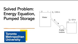
Let’s look at a practical problem. A pipe of 0.7 m diameter is 6 km long with a head difference of 30 m. What would our first step be?
We need to calculate the total head loss first.
Correct! We apply the Darcy-Weisbach equation to compute the major losses. Then, we account for minor losses. Can anyone calculate the major loss using a given friction factor?
If the friction factor is 0.024, I believe the head loss would be... (completes calculation).
Great job! These calculations are crucial as they reveal how energy is dissipated in the system. Always keep practicing with real data.
Introduction & Overview
Read summaries of the section's main ideas at different levels of detail.
Quick Overview
Standard
The section outlines the key principles of head loss, differentiating between major losses due to friction and minor losses due to bends, valves, and other factors. The application of Bernoulli’s equations for calculating pressure and flow rates is emphasized, along with practical examples to reinforce understanding.
Detailed
Head Losses
In fluid mechanics, understanding head losses is crucial for analyzing fluid flow through pipes. Head loss can be divided into two main categories: major losses, which occur due to friction along the length of the pipe, and minor losses, which arise from fittings such as bends, valves, and entrances/exits.
Major Pipe Head Loss
The major head loss is computed using the Darcy-Weisbach equation, which accounts for friction in the pipe. It's expressed as:
$$ h_f = f \frac{L}{D} \frac{V^2}{2g} $$
where:
- $h_f$ is the head loss due to friction,
- $f$ is the friction factor,
- $L$ is the length of the pipe,
- $D$ is the diameter of the pipe,
- $V$ is the average velocity of the fluid,
- $g$ is the acceleration due to gravity.
Minor losses can be calculated for particular fittings using coefficients. These losses affect the total head loss and need to be accounted for when applying Bernoulli’s equations to compute the pressure at various points in a piping system.
Examples presented in this section include calculation scenarios for head loss in horizontal pipes with various flow rates, allowing for practical application of these theoretical concepts. Overall, this section serves to integrate the fundamental theory of head loss into the practical aspects of fluid dynamics.
Youtube Videos


![[MAE 242] Pipe flow with major and minor head losses](https://img.youtube.com/vi/WH1fn6dMYiw/mqdefault.jpg)


Audio Book
Dive deep into the subject with an immersive audiobook experience.
Understanding Head Losses
Chapter 1 of 5
🔒 Unlock Audio Chapter
Sign up and enroll to access the full audio experience
Chapter Content
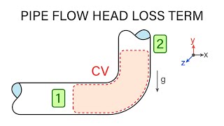
So that means I know the head losses that is what is computed here by substituting this value. There will be minor losses like bend losses, valve losses, the entry and exit losses all the components, this entry and exit loss we do not consider it here only the bend loss and valve loss we compute it which we have these values.
Detailed Explanation
In fluid mechanics, head loss refers to the energy loss of fluid due to friction and other factors as it moves through a pipe or duct. It can be classified into two main categories: major losses and minor losses. Major losses are typically caused by friction along the length of the pipe, while minor losses occur at fittings, bends, valves, and other components. In this introductory statement, the focus is directed towards understanding how these losses are calculated, specifically highlighting that only bend and valve losses will be considered in the analysis.
Examples & Analogies
Think of water flowing through a garden hose. If the hose is long and has several bends, it will be harder for the water to flow compared to a straight hose. The energy lost due to the friction with the hose walls and the bends in the hose represents head loss.
Major Pipe Head Loss Calculation
Chapter 2 of 5
🔒 Unlock Audio Chapter
Sign up and enroll to access the full audio experience
Chapter Content
Major pipe head loss (due to friction):
\[ h_f = \frac{f L V^2}{2gD} \]
Where:
- \( h_f \) is the head loss due to friction
- \( f \) is the friction factor
- \( L \) is the length of the pipe
- \( V \) is the velocity of fluid
- \( g \) is the acceleration due to gravity
- \( D \) is the diameter of the pipe
(Refer Slide Time: 50:39)
Detailed Explanation
The equation provided is used to calculate the major head loss (friction loss) in a pipe. It consists of several variables:
- The friction factor (f) depends on the type of fluid and the roughness of the pipe.
- The length of the pipe (L) significantly influences the head loss; longer pipes experience greater losses.
- The fluid velocity (V) and pipe diameter (D) are also critical; higher speeds and larger diameters typically reduce friction losses.
This formula is essential for engineers when designing piping systems to ensure adequate pressure and flow rates in systems.
Examples & Analogies
Imagine water flowing through two different lengths of tubing. If you have one tube that is 10 meters long and another that is 100 meters long, the longer tube will require more energy to push the water, portraying how length affects head loss in pipelines.
Minor Losses Definition
Chapter 3 of 5
🔒 Unlock Audio Chapter
Sign up and enroll to access the full audio experience
Chapter Content
Minor losses:
\[ h_{minor} = K \frac{V^2}{2g} \]
Where \( K \) is the loss coefficient for specific fittings or components.
If are considering that the loss components will get it this much is the minor losses.
Detailed Explanation
Minor losses are losses that occur at points of disruption in the flow path, such as bends, valves, and fittings. Each of these elements has a loss coefficient (K), which quantifies the additional head loss attributed to that component. The formula shows that head loss due to minor losses can be calculated using the velocity of the fluid and the loss coefficient. Minor losses can sometimes be neglected in comparison to major losses but can be significant in highly detailed designs of piping systems.
Examples & Analogies
Consider a water slide that makes several sharp turns. The sharp turns represent minor losses, as they disrupt the smooth flow of water, causing it to slow down and lose energy. The more turns, similar to fittings in a pipe, the more potential energy loss in the system.
Using Bernoulli’s Equation for Pressure Computation
Chapter 4 of 5
🔒 Unlock Audio Chapter
Sign up and enroll to access the full audio experience
Chapter Content
Now we are substituting Bernoulli’s equations, the modified Bernoulli’s equations to compute what could be the pressure. So I am not going more detail as you can read this ppt to get these details.
Detailed Explanation
Bernoulli’s equation is used widely in fluid dynamics and relates the pressure at different points within a flowing fluid. It considers factors like height (potential energy), velocity (kinetic energy), and energy losses (head losses). By inserting previously calculated values into this equation, one can analyze how head losses affect pressure within the system. This practical application helps in understanding the operational parameters for any fluid system.
Examples & Analogies
Using a water timer at a theme park, when the water is flowing quickly, it features lower pressure in certain areas, reflecting Bernoulli’s principle. Just like a roller coaster that has high speed at the apex and lower pressure around the curves of the ride.
Calculating Pressure at Point B
Chapter 5 of 5
🔒 Unlock Audio Chapter
Sign up and enroll to access the full audio experience
Chapter Content
Pressure at B (using Bernoulli’s eq):
\[ P_B = P_A + \frac{\rho g h - h_f}{\text{Total Head}} \]
(Refer Slide Time: 50:57)
Detailed Explanation
To calculate the pressure at a certain point in a fluid system (Point B), we modify Bernoulli’s equation to account for altitude (potential energy measured by height) and head loss (from friction and fittings). The pressure at Point B can be found by adding initial pressure and the effect of energy differences considering the losses sustained over the distance traveled in the fluid flow. This practical approach allows for effective pressure modification throughout the system.
Examples & Analogies
Imagine you're filling a balloon with water and you notice that if you squeeze the tube (representing the head loss), less water goes into the balloon (lower pressure). Similarly, in piping systems, understanding how to calculate the remaining pressure after head loss helps determine how and when to change the flow dynamics.
Key Concepts
-
Major Losses: Losses in energy due solely to pipe friction.
-
Minor Losses: Losses triggered by components like valves and bends.
-
Darcy-Weisbach Equation: A crucial equation used to quantify friction losses in pipes.
-
Energy Conservation: Underpins calculations of head loss using Bernoulli's principle.
Examples & Applications
A pipe system connecting two reservoirs where initial and final pressures differ due to head loss.
Calculating expected pressure after accounting for a valve and bend in pipe flow.
Memory Aids
Interactive tools to help you remember key concepts
Rhymes
When friction flows, head loss grows, through pipes beautiful it goes.
Stories
Imagine a river flowing downstream; when it encounters rocks (minor losses) or mudslide (major losses), its speed and level change, thereby illustrating head loss.
Memory Tools
Remember M.E.E. for Major and Minor Energy Loss! Major = Length, Minor = Fittings.
Acronyms
Use 'FLOW' to remember
Friction
Losses
Openings
Water for head loss factors.
Flash Cards
Glossary
- Head Loss
The loss of energy in a fluid flow system, represented as a height of fluid.
- DarcyWeisbach Equation
An equation used to calculate pressure loss due to friction in a pipe.
- Friction Factor
A dimensionless number that represents the frictional resistance in a pipe.
- Bernoulli’s Equation
An equation that describes the conservation of energy in fluid flow.
- Minor Losses
Head losses due to fittings, valves, and other accessories in the pipe system.
Reference links
Supplementary resources to enhance your learning experience.