
Head Loss in Pipes
Enroll to start learning
You’ve not yet enrolled in this course. Please enroll for free to listen to audio lessons, classroom podcasts and take practice test.
Interactive Audio Lesson
Listen to a student-teacher conversation explaining the topic in a relatable way.
Understanding Head Loss in Pipes
🔒 Unlock Audio Lesson
Sign up and enroll to listen to this audio lesson

Today, we're going to explore a very important concept in fluid mechanics—head loss in pipes. Can anyone tell me why head loss might be significant when designing pipe networks?

It impacts how efficiently liquids or gases can be transported, right?
Exactly! Understanding head loss helps engineers design more energy-efficient systems. The head loss will mainly be affected by factors like fluid velocity, viscosity, and flow turbulence. Let’s remember that—VFT: Velocity, Friction, and Turbulence.

What kind of experiments help us understand head loss better?
Great question! Various experiments, like the Reynolds apparatus, visually demonstrate laminar and turbulent flow, allowing us to quantify energy losses. Can anyone describe what they think laminar flow looks like?

I think it's smooth and orderly, like layers sliding over each other, right?
That’s correct! In laminar flows, patterns remain organized, while in turbulent flows, we see chaos and mixing.

And how does that affect head loss?
In turbulent flow, head loss increases due to additional friction, as chaotic interactions make fluid layers move erratically. Always remember: T here’s a lot more friction happening in turbulent flows!
In summary: Head loss is crucial for designing effective pipe systems, specifically influenced by velocity, turbulence, and friction.
Laminar vs. Turbulent Flow
🔒 Unlock Audio Lesson
Sign up and enroll to listen to this audio lesson

Let’s delve deeper into the differences between laminar and turbulent flow. Can someone define laminar flow for us?
Isn’t it when the flow is smooth and layers of fluid move in parallel streams?
Absolutely! In laminar flow, the Reynolds number is less than 2300. Now, what happens at the critical Reynolds number indicating transition?
It goes from laminar to turbulent as inertia forces increase relative to viscous forces.
Correct! Just remember this transition happens between 2300 and 4000—let's call it the 'T-zone for turbulence'. What effect does this transition have on head loss?
Head loss increases significantly in turbulent flow because of the chaotic motions.
Right! Turbulent flow results in a greater head loss compared to laminar flow due to increased friction. Always keep this distinction clear: Laminar = smooth and Turbulent = chaotic!
To summarize: Laminar flows are ordered and have less head loss; turbulent flows are chaotic and have more head loss.
Reynolds Number and Its Importance
🔒 Unlock Audio Lesson
Sign up and enroll to listen to this audio lesson
Now let's discuss Reynolds number. Who can explain what Reynolds number quantifies?
It’s the ratio of inertial forces to viscous forces!
Exactly! It helps us understand whether our flow is laminar or turbulent. How do we calculate it?
Using the formula: Re = (density * velocity * diameter) / viscosity.
That’s right! And the thresholds of Re tell us about flow regimes: less than 2300 for laminar and more than 4000 for turbulent. Can anyone provide a practical scenario where knowing this would be important?
In industrial applications, like water supply systems, it’s crucial to know if the flow remains efficient or not.
Exactly! Engineers need to select pipe sizes and materials based on these flow characteristics. In essence: Reynolds number impacts head loss and flow efficiency.
To summarize: Reynolds number signifies flow type and is essential for designing flow systems.
Practical Applications and Experimental Insights
🔒 Unlock Audio Lesson
Sign up and enroll to listen to this audio lesson
Let’s shift gears to discuss how experiments enhance our understanding of head loss. Why are practical experiments important?
They provide real-world data to validate theoretical calculations.
Exactly! For example, the Reynolds apparatus allows us to visualize flow patterns. What do we observe from such experiments?
We can see how dye diffuses, indicating flow types and transition zones.
Correct! These observations give us valuable insights into energy losses due to turbulent flow. How do those energy losses relate to industrial designs?
We can optimize pipe diameters and materials based on the flow characteristics we observe!
Well said! By applying these principles, engineers develop efficient transportation systems for liquids and gases.
In summary: Experimental approaches are invaluable for understanding and minimizing head loss in piping systems.
Introduction & Overview
Read summaries of the section's main ideas at different levels of detail.
Quick Overview
Standard
This section introduces the concept of head loss in pipe systems, discussing its significance in fluid mechanics, particularly in the context of laminar and turbulent flow behavior. It also emphasizes the critical role of experiments in understanding energy losses and designing efficient piping systems.
Detailed
In fluid mechanics, head loss refers to the energy loss that fluid experiences due to friction and turbulence as it travels through pipes. This section elaborates on the characteristics of laminar and turbulent flows, highlighting how various factors such as flow velocity, viscosity, and Reynolds number impact head loss. A key focus is on the practical importance of designing energy-efficient pipe networks for the transportation of liquids and gases. The section also covers the experimental approaches that aid in quantifying head loss and improving piping system designs.
Youtube Videos

![[MAE 242] Pipe flow with major and minor head losses](https://img.youtube.com/vi/WH1fn6dMYiw/mqdefault.jpg)


Audio Book
Dive deep into the subject with an immersive audiobook experience.
Understanding Head Loss
Chapter 1 of 3
🔒 Unlock Audio Chapter
Sign up and enroll to access the full audio experience
Chapter Content
Head loss in pipes refers to the reduction in the total mechanical energy of the fluid as it moves through the pipe, primarily due to friction. This loss can be attributed to various factors including pipe roughness, flow velocity, and fluid viscosity.
Detailed Explanation
Head loss is essentially the energy loss that the fluid experiences when it flows through a pipe. As the fluid moves, it encounters resistance due to friction between the fluid particles and the pipe walls. This resistance leads to a decrease in the total mechanical energy of the fluid, which is quantified as head loss. There are different types of head loss, such as 'major loss' which occurs due to friction along a length of pipe, and 'minor loss' which occurs due to fittings, bends, or valves in the pipe system. Understanding head loss is crucial for designing efficient piping systems that ensure adequate fluid transport while minimizing energy consumption.
Examples & Analogies
Think of head loss like the effort it takes to walk through a crowded room. If there are many people (friction) in the room, you'll have to push your way through, which takes more energy and slows you down (loss of mechanical energy). Similarly, as fluid moves through a pipe with obstacles (like rough walls or bends), it loses energy due to friction, resulting in head loss.
Factors Affecting Head Loss
Chapter 2 of 3
🔒 Unlock Audio Chapter
Sign up and enroll to access the full audio experience
Chapter Content
The degree of head loss in a pipe can be influenced by several factors including the flow rate of the fluid, the viscosity of the fluid, the roughness of the pipe's interior surface, and changes in the pipe diameter.
Detailed Explanation
Several factors contribute to head loss in pipes. First, the flow rate affects how quickly fluid moves through the pipe; higher flow rates can increase friction and thus lead to greater head loss. Second, the viscosity of the fluid plays a key role; more viscous fluids resist motion more than less viscous ones, which can lead to increased head loss. Additionally, the roughness of the pipe's interior surface also affects head loss. A smoother pipe surface reduces friction, while a rough surface increases it. Lastly, variations in pipe diameter can impact flow velocity, causing changes in head loss. A sudden decrease in diameter can lead to increased speeds and more turbulence, amplifying head loss.
Examples & Analogies
Imagine trying to slide down a slide at a playground. If the slide is smooth, you glide quickly without much effort (low head loss). But if the surface is rough and bumpy, you slow down and struggle to slide (high head loss). Similarly, in a pipe, smooth surfaces and optimal flow rates lead to less friction and energy loss.
Calculation of Head Loss
Chapter 3 of 3
🔒 Unlock Audio Chapter
Sign up and enroll to access the full audio experience
Chapter Content
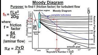
Head loss in pipes can be calculated using the Darcy-Weisbach equation, which states that the head loss (h_f) is proportional to the friction factor (f), the length of the pipe (L), the velocity of the fluid (v), and inversely proportional to the diameter of the pipe (D).
Detailed Explanation
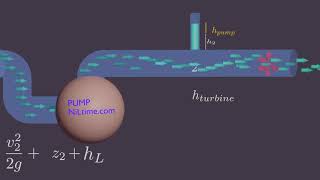
The Darcy-Weisbach equation for calculating head loss is given by: \(h_f = f \frac{L}{D} \frac{v^2}{2g}\), where \(h_f\) is the head loss due to friction, \(f\) is the Darcy-Weisbach friction factor (dependent on flow regime and pipe roughness), \(L\) is the length of the pipe, \(D\) is the diameter of the pipe, \(v\) is the flow velocity, and \(g\) is the acceleration due to gravity. This equation helps engineers and designers calculate how much energy they need to overcome losses in the system and to ensure that pumps and other equipment are selected appropriately for maintaining desired flow rates.
Examples & Analogies
Consider riding a bike up a hill. The steeper the hill (analogous to higher head loss), the more energy you will need to expend to reach the top. Similarly, the Darcy-Weisbach equation helps you calculate how much energy (or 'head') is necessary to overcome the frictional losses in a pipe system and maintain the desired flow.
Key Concepts
-
Head Loss: Energy loss due to friction and turbulence in piping systems.
-
Reynolds Number: A key factor that determines whether flow is laminar or turbulent.
-
Laminar vs. Turbulent Flow: Their characteristics and implications for head loss.
-
Experimental Insights: The role of experiments in understanding and designing efficient pipe systems.
Examples & Applications
In a plumbing system, choosing the right diameter of pipes based on Reynolds number ensures minimal head loss, leading to lower energy costs.
Observing dye diffusion in a water channel experiment can show a clear transition from laminar to turbulent flow, reinforcing the understanding of head loss.
Memory Aids
Interactive tools to help you remember key concepts
Rhymes
In a pipe of flow, let’s not lose, Keep smooth, it’s best, that's your good muse. For turbulent might let energy abuse.
Stories
Imagine a water park slide: The smooth path lets you glide gracefully (laminar). The bumpy ride, filled with swirls and echoes, shows turbulence and lots of splashes!
Memory Tools
Remember 'FVT' - For Velocity, Friction, Turbulence, are key to understanding head loss.
Acronyms
Use 'HVE' to recall
Head loss
Velocity effects
and the role of turbulent flows in pipes.
Flash Cards
Glossary
- Head Loss
The reduction in the total mechanical energy of the fluid due to friction and turbulence as it flows through a pipe.
- Laminar Flow
A flow regime characterized by smooth, orderly movement of fluid in parallel layers.
- Turbulent Flow
A chaotic flow regime where fluid undergoes irregular fluctuations and mixing.
- Reynolds Number
A dimensionless number used to predict flow regimes, calculated as the ratio of inertial forces to viscous forces.
- Friction Loss
Energy loss due to friction between the fluid and the pipe wall.
Reference links
Supplementary resources to enhance your learning experience.