
Lab Work on Integral Control Circuits
Interactive Audio Lesson
Listen to a student-teacher conversation explaining the topic in a relatable way.
Overview of Integral Control Circuits
🔒 Unlock Audio Lesson
Sign up and enroll to listen to this audio lesson

Today, we're going to discuss integral control circuits. Can anyone tell me what they think happens in an integral control system?

I think it relates to how the system reacts over time to the error signal.
Exactly! Integral control allows systems to consider the accumulation of error over time, aiming to eliminate steady-state errors. Remember the formula for the control output, which includes integral calculations. What does that formula look like?

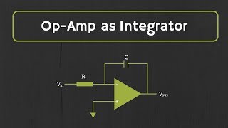
It's Vout(t) = (1/RC) ∫E(t) dt, right?
Spot on! This equation is fundamental to our circuit design. It shows how the error signal impacts our output over time. Let’s move on to our lab work.
Materials Needed for the Lab
🔒 Unlock Audio Lesson
Sign up and enroll to listen to this audio lesson

For today's lab, we'll need specific materials. Can anyone name one item we'll be using?

We’ll use an Op-Amp, like the LM741?
Correct! We also need resistors, capacitors, and a signal generator. Each of these components plays a crucial role in our circuit. Why do we need resistors and capacitors?

Resistors help to set the feedback and gain, while capacitors are essential for the integration process.
Exactly! This combination aids in managing how we accumulate error over time. Let's move on to the procedure.
Procedure for Building the Circuit
🔒 Unlock Audio Lesson
Sign up and enroll to listen to this audio lesson
Now, let's go through the procedure for our lab work. Can anyone summarize the first step?
We need to construct the integral control circuit by connecting the Op-Amp and components.
That's right! Ensure that the error signal input is correctly connected. Why is it important to apply an error signal?
It's how we determine if our circuit is functioning as intended and correcting the output!
Exactly! After applying the error signal, we will observe the output over time. Who can explain why observing the response is necessary?
To see how well the circuit integrates the error and corrects any steady-state errors!
Great job! Now, let’s head to the lab and begin!
Data Collection and Analysis
🔒 Unlock Audio Lesson
Sign up and enroll to listen to this audio lesson
After the experiment, we'll need to collect data on our output response. What do you think we should look for in our analysis?
We should check if the output stabilizes at the correct setpoint and how quickly it corrects any errors.
Exactly! Analyzing how quickly the integral control responds to steady-state errors will inform us about the system’s performance. We'll also plot these results to visualize our findings.
Will we need to adjust anything during our measurements?
Great question! Depending on our results, we might adjust values of resistors or capacitors for optimized performance.
Introduction & Overview
Read summaries of the section's main ideas at different levels of detail.
Quick Overview
Standard
In this section, students are guided to design and build an integral control circuit focusing on the accumulated error signal over time. Key objectives include understanding how the integral control helps eliminate steady-state errors and monitoring the system’s performance through practical measurement.
Detailed
Lab Work on Integral Control Circuits
In this section, we delve into the practical application of integral control systems using operational amplifiers (Op-Amps). The objective is to design and build an integral control circuit that regulates an output based on the error signal accumulated over time. Integral control is crucial in systems that demand precision and stability by eliminating steady-state errors that could hinder performance.
Key Objectives
- Design: Construct an integral control circuit utilizing an Op-Amp and basic electronic components.
- Application: Implement the circuit in a real-world test setting to observe how it reacts to error signals.
- Measurement: Monitor and analyze the output response as the error signal is integrated over time to establish how effectively the circuit corrects steady-state errors.
Significance
This lab work is integral to understanding Op-Amps in control circuits, emphasizing their role in producing reliable outputs through the integration of accumulated errors, thus leading to more refined and stable control systems.
Youtube Videos
Audio Book
Dive deep into the subject with an immersive audiobook experience.
Objective of the Lab Work
Chapter 1 of 3
🔒 Unlock Audio Chapter
Sign up and enroll to access the full audio experience
Chapter Content
● Objective: Design and build an integral control circuit to regulate the system based on the accumulated error signal.
Detailed Explanation
The main goal of this lab work is to create an integral control circuit. This type of circuit aims to regulate a system by utilizing the accumulated error signal over time. Essentially, the circuit will help correct any discrepancies between the desired output (setpoint) and the actual output by integrating the error over a specified period. This method is particularly effective because it helps eliminate steady-state errors, ensuring the system reaches and maintains the desired setpoint.
Examples & Analogies
Consider a thermostat in your home. Imagine the thermostat is set to maintain a specific temperature. If the temperature in the house is consistently below the setpoint (let's say 72°F), the thermostat gradually increases the heating to raise the temperature. If for some reason the temperature doesn't reach 72°F, the thermostat will continue to adjust the heating because it remembers that lower temperature over time, ensuring your home becomes warm enough.
Materials Needed for the Lab Work
Chapter 2 of 3
🔒 Unlock Audio Chapter
Sign up and enroll to access the full audio experience
Chapter Content
● Materials:
1. Op-Amp (e.g., LM741)
2. Resistors and capacitors for integration
3. Signal generator and oscilloscope
4. Test system or motor
Detailed Explanation
To successfully conduct the lab work on the integral control circuit, several essential materials are required. An operational amplifier (Op-Amp), like the LM741, serves as the core component for the circuit. Resistors and capacitors will be used in configuring the integrator part of the circuit, which allows for the integration of the error signal. A signal generator provides the requisite error signal input, and an oscilloscope is necessary to visualize the circuit's output response over time. Additionally, a test system or motor will be needed to evaluate how well the circuit regulates control.
Examples & Analogies
Think of this lab setup like cooking. Just as you need specific ingredients (like flour, eggs, and sugar) to bake a cake, in this lab, you need specific electronic components to build the circuit. Each ingredient plays a vital role in achieving the final outcome, whether it’s a tasty cake or a well-functioning control circuit.
Procedure for the Lab Work
Chapter 3 of 3
🔒 Unlock Audio Chapter
Sign up and enroll to access the full audio experience
Chapter Content
● Procedure:
1. Construct the integral control circuit and apply an error signal.
2. Observe the output response over time as the error signal is integrated.
3. Measure how the system corrects steady-state errors.
Detailed Explanation
The procedure for the lab work involves several clear steps. First, you will build the integral control circuit using the materials gathered. Next, apply a known error signal to the circuit, allowing it to function and integrate that signal over time. As you monitor the output using an oscilloscope, take note of how the output changes as the error accumulates. Finally, measure the extent to which the system corrects any steady-state errors that may exist, determining how effectively the integral control is working.
Examples & Analogies
Imagine you are adjusting the volume of a speaker based on background noise. Initially, if the noise from outside increases, you might turn up the volume just a bit. However, after a while, if the noise continues, you adjust the volume significantly to compensate for that persistent interference. In this procedure, just like adjusting the volume over time, you observe how the control circuit responds to the cumulative error and gradually makes adjustments to correct it.
Key Concepts
-
Integral Control: Utilizes the accumulation of error over time to eliminate steady-state errors.
-
Op-Amp Configuration: In an integrator configuration, which helps improve control output based on integrated error.
-
Steady-State Response: The analysis of how quickly and effectively the system achieves stability.
Examples & Applications
An integral control circuit might be used in a temperature control system to ensure that the temperature not only reaches the setpoint but maintains it over time without fluctuation.
In position control of a motor, the integral control allows the system to adjust the position based on past errors, ensuring that the motor reaches its desired location accurately.
Memory Aids
Interactive tools to help you remember key concepts
Rhymes
In control circuits, integrals play, Steady-state errors keep at bay.
Stories
Imagine a sailor navigating a ship; the captain counts every wave (error) hitting the hull. Over time, he learns to adjust his sails (output) based on all the waves he has counted, allowing the ship to cut through the water smoothly.
Memory Tools
Remember 'ICE': Integrate, Correct, Eliminate - the steps in integral control.
Acronyms
SCER
Steady-state errors Corrected with Error integration Response
capturing the essence of an integral control circuit.
Flash Cards
Glossary
- Integral Control
A control system where the output is proportional to the accumulated sum of the error signal over time, helping eliminate steady-state errors.
- OpAmp
Operational Amplifier, a voltage amplifier with differential inputs and a single-ended output used in various electronic circuits.
- Error Signal
The difference between the desired setpoint and the actual output, which is used to adjust the control system.
- Integrator Configuration
A configuration of an Op-Amp where the input signal is integrated to produce a continuous output based on past error values.
- SteadyState Error
The persistent difference between the desired output and actual output in a control system when it reaches a steady state.
Reference links
Supplementary resources to enhance your learning experience.