
Design of Integral Control Circuits
Interactive Audio Lesson
Listen to a student-teacher conversation explaining the topic in a relatable way.
Introduction to Integral Control Circuits
🔒 Unlock Audio Lesson
Sign up and enroll to listen to this audio lesson

Today, we're discussing integral control circuits. Can anyone tell me what you understand by 'integral control'?

Is it about eliminating errors in a system over time?
Exactly! Integral control aims to eliminate steady-state errors by accumulating the error signal over time. This means it adjusts the output based not just on the error at one moment, but on the history of errors.

How does the Op-Amp fit into this process?
Good question! The Op-Amp acts as an integrator in this circuit, processing the error signal to produce a control output that adjusts accordingly.

Can you give an example of where this might be used?
Certainly! For example, in a position control system, integral control helps ensure that a mechanical system reaches and maintains a set position by considering past discrepancies.
Let’s recap: Integral control aims to reduce steady-state errors and uses Op-Amps configured for integration. Write down examples of where you'd like integral control applied!
Key Equation for Integral Control Output
🔒 Unlock Audio Lesson
Sign up and enroll to listen to this audio lesson

Now let’s look at the mathematical representation of the control output in an integral control circuit. The equation is: $V_{out}(t) = \frac{1}{RC} \int E(t) \, dt$. What does this mean?

So, $V_{out}(t)$ is the output, and $E(t)$ is the error signal?
Correct! The terms R and C are the resistor and capacitor values in the feedback loop. Can someone tell me how the output changes based on these values?
If R or C increases, the output response will be slower, right?
Exactly! A larger RC value means slower integration, which can affect how quickly the system responds to changes. This is important for tuning the circuit to achieve desired performance.
As a quick summary: The equation for integral control output reflects how errors influence the output over time. Make sure to jot down the components of this equation!
Applications of Integral Control Circuits
🔒 Unlock Audio Lesson
Sign up and enroll to listen to this audio lesson
Let’s delve into the applications of integral control circuits. Can someone provide an example of precision systems that might need integral control?
Temperature control systems could use integral control to adjust and maintain the temperature.
That's spot on! Integral control helps maintain precise temperature settings by correcting any persistent offsets. How about another example?
What about in robotics where precise positioning is crucial?
Exactly! In robotics, integral control ensures that a robot maintains its position by continually correcting any deviation based on accumulated errors.
To summarize our discussion: Integral control is essential in applications like temperature regulation and robotics for achieving precision by minimizing steady-state errors. Think of other systems that could benefit and share during our next class!
Lab Work on Integral Control Circuits Design
🔒 Unlock Audio Lesson
Sign up and enroll to listen to this audio lesson
Now that we understand integral control, let’s go over the lab work. Who can tell me what materials we’ll need to design an integral control circuit?
We will need an Op-Amp, resistors, capacitors, and a signal generator.
Correct! The Op-Amp is critical in our circuit setup. What will we do first when constructing the circuit?
We will connect the Op-Amp in an integrator configuration, right?
Yes! You’ll apply an error signal and observe the output. Can someone summarize the key step after that?
We need to measure how the output changes over time and see how it corrects for any steady-state errors.
Great! Remember, practical application helps reinforce our theoretical knowledge. Review previous lab experiences related to feedback control and come prepared with questions next time!
Introduction & Overview
Read summaries of the section's main ideas at different levels of detail.
Quick Overview
Standard
Integral control circuits are crucial in applications where eliminating steady-state errors is vital. This section discusses the basic design of these circuits, the key equations involved, and their practical applications, providing a clear understanding of how accumulated errors shape system outputs over time.
Detailed
Design of Integral Control Circuits
Integral control circuits utilize operational amplifiers (Op-Amps) to maintain system output by addressing steady-state errors. In this configuration, the control output is dependent on the accumulated error over time. The primary aim of integral control is to adjust for persistent discrepancies between the desired setpoint and the actual output, effectively eliminating these errors in precision systems.
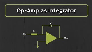
Basic Design
The Op-Amp is set up in an integrator configuration, where the error signal defined as the difference between the setpoint and the actual output is integrated over time. This integration leads to a control output that continuously adjusts to keep the system on target.
Key Equation
The control output can be mathematically described by:
$$V_{out}(t) = \frac{1}{RC} \int E(t) \, dt$$
In this equation:
- $V_{out}(t)$ represents the control output,
- $R$ and $C$ are the resistor and capacitor values in the feedback loop, respectively,
- $E(t)$ indicates the error signal.
Applications
Integral control is commonly found in precision systems, such as:
- Systems that aim to eliminate steady-state errors effectively.
- Position control applications, ensuring that mechanical systems stay at a desired position by accounting for accumulated error over time.
Youtube Videos
Audio Book
Dive deep into the subject with an immersive audiobook experience.
Basic Design of Integral Control Circuits
Chapter 1 of 3
🔒 Unlock Audio Chapter
Sign up and enroll to access the full audio experience
Chapter Content
The Op-Amp is configured in an integrator configuration, where the error signal is integrated over time to produce an output that increases or decreases based on the accumulated error.
Detailed Explanation
In an integral control circuit, the main objective is to manage the error signal over time. This is achieved through an integrator configuration, where the operational amplifier (Op-Amp) sums the error signal continuously. Instead of reacting immediately to the error, the circuit collects this error signal over a period, allowing for a more comprehensive adjustment of the control output. This design helps in eliminating any steady-state errors that may occur when the system is operating at a setpoint.
Examples & Analogies
Think of a large water tank that needs to stay at a specific level. Just like a water tank that continuously fills up whenever there’s a deficit, an integral control circuit collects the error (the difference between the set level and the actual level) over time. If the water level drops due to leaks or evaporation, the tank’s valve opens wider and stays open longer, gradually filling the tank back to the desired level.
Key Equation for Integral Control Circuits
Chapter 2 of 3
🔒 Unlock Audio Chapter
Sign up and enroll to access the full audio experience
Chapter Content
The control output is given by:
Vout(t)=1RC∫E(t) dt
Where:
- Vout(t) is the control output,
- R and C are the resistor and capacitor in the feedback loop,
- E(t) is the error signal.
Detailed Explanation
The equation for the control output, Vout(t), demonstrates how the output of the integral control circuit relates to the accumulated error signal. Here, R (resistor) and C (capacitor) play crucial roles in determining the rate at which the error is integrated. The integration sign (∫) indicates that the output is based on the sum of the error signal over time. Hence, as time progresses, the current error impacts the output based on the past values rather than only the current error, allowing for adjustments that consider historical performance.
Examples & Analogies
Imagine tracking how much you eat throughout the day. Instead of just looking at how much food is on your plate right now (current error), you might think about all the meals you had earlier (cumulative error). By keeping a mental note of your total intake (integral of your consumption), you make more informed decisions about your next meal. Similarly, the integral control circuit continuously evaluates the 'diet' of the error signal to adjust output accordingly.
Applications of Integral Control Circuits
Chapter 3 of 3
🔒 Unlock Audio Chapter
Sign up and enroll to access the full audio experience
Chapter Content
Integral control is used in systems where the goal is to eliminate steady-state errors.
- Precision systems: Used in systems where the goal is to eliminate steady-state errors.
- Position control: Ensures that a mechanical system reaches and stays at a set position by accumulating error over time.
Detailed Explanation
Integral control circuits find their applications in situations where maintaining accuracy over time is critical. For example, in precision systems like robotic arms or CNC machines, even minor steady-state errors can lead to performance issues or product defects. By integrating the error over time, these systems can adjust continuously and thus correct any bias without overshooting the target. Additionally, in position control applications, integral control ensures that once a mechanical system reaches its designated position, it can remain there with minimal deviation by compensating for any persistent errors.
Examples & Analogies
Consider a skilled archer aiming at a target. If the arrow always lands slightly to the left (a steady-state error), the archer might subconsciously adjust their aim over time, taking note of where arrows land after many shots. This adjustment represents the cumulative learning—integrating all previous shots to refine future accuracy. Just like this archer, the integral control circuit leverages past error data to improve its present performance.
Key Concepts
-
Integral Control: A method to eliminate steady-state errors by integrating the error signal over time.
-
Op-Amp Integrator: A configuration of an Op-Amp that produces an output proportional to the integral of its input signal.
-
Error Signal: The difference between the setpoint and the actual output used in control systems.
Examples & Applications
An integral control circuit is utilized in automated temperature control systems to maintain the desired temperature by correcting lingering discrepancies.
In robotics, integral control circuits ensure that the robot maintains its position by accumulating errors and adjusting the output appropriately over time.
Memory Aids
Interactive tools to help you remember key concepts
Rhymes
For integral gains you can't forsake, Over time, the error you'll take!
Stories
Imagine a boat trying to reach a dock. The captain keeps a log of how far off they are and adjusts the course based on the overall drift, ensuring they arrive perfectly.
Memory Tools
Remember 'IER' for Integral’s goal: Integrate, Eliminate, Regulators of control!
Acronyms
DER for 'Dynamic Error Reduction' — the aim of integral control.
Flash Cards
Glossary
- Integral Control
A control strategy that adjusts the output based on the accumulated sum of the error signal over time, aiming to eliminate steady-state errors.
- OpAmp
An operational amplifier used in various electronic circuits, including integrators for processing signals.
- Error Signal
The difference between the desired output (setpoint) and the actual output in a control system.
- Integrator Configuration
A setup where the Op-Amp integrates the input signal over time to produce a corresponding output.
- Feedback Loop
The path for a signal to return to the input of a system, helping to maintain desired control levels.
- SteadyState Error
The difference that remains between the desired setpoint and the actual output after a system has stabilized.
Reference links
Supplementary resources to enhance your learning experience.