
Op-Amp-based Proportional Control Circuits
Interactive Audio Lesson
Listen to a student-teacher conversation explaining the topic in a relatable way.
Introduction to Proportional Control
🔒 Unlock Audio Lesson
Sign up and enroll to listen to this audio lesson

Today, we'll explore proportional control circuits that utilize Operational Amplifiers. Can anyone tell me what an Op-Amp does?

An Op-Amp amplifies the difference between its input signals?
Exactly! In proportional control systems, the output is influenced by the error signal, which is the difference between the desired setpoint and the actual output. This ensures the system can adjust accordingly.

So, the output changes based directly on how far we are from our goal?
Yes! This is the essence of proportional control, and it can be expressed with our key equation. Who remembers it?

I believe it's Vout = Kp × E(t)!
Spot on! Here, Kp is the proportional gain, and E(t) is the error signal.

What kind of applications are we seeing this in?
Great question! We see these in temperature control and motor speed regulation. Let's remember: Proportional Control = Error Signal Adjustment.
Design and Application
🔒 Unlock Audio Lesson
Sign up and enroll to listen to this audio lesson

Now that we understand the basics, let’s explore how we actually design a proportional control circuit.
What’s the first step in the design?
First, we configure the Op-Amp in a feedback loop. How does this feedback loop help us?
It helps adjust the output in response to the error signal!
Exactly! So when we apply a known setpoint, what happens to the output?
The output should adjust according to how far we are from that setpoint?
Correct! This adjustment through the proportional gain helps us maintain system stability. Before we move on to applications, can anyone summarize what Kp does?
It's the factor that scales our error signal to create the final output!
Yes, well done! Remember: Feedback Loop = Error Adjustment.
Practical Lab Work
🔒 Unlock Audio Lesson
Sign up and enroll to listen to this audio lesson
Now it’s time for some hands-on experience! We’ll build a proportional control circuit together. What materials will we need?
We’ll need an Op-Amp, resistors, a signal generator, and an oscilloscope!
Exactly! The goal is to measure the output based on a known setpoint. Who can explain the process to start?
We first construct the circuit by wiring the Op-Amp and connecting the error signal input.
Great! After setting up, what should we observe when we apply the setpoint?
The output should change as we adjust Kp and observe how it reacts to error.
Exactly! Observing this response will solidify our understanding of proportional control. Remember: Hands-on trials confirm theory!
Introduction & Overview
Read summaries of the section's main ideas at different levels of detail.
Quick Overview
Standard
In proportional control systems, the output is adjusted in proportion to the input error signal, which is the difference between the desired and actual values. These circuits, predominantly designed using operational amplifiers, are critical for applications such as temperature and motor control, and they enhance system stability.
Detailed
Op-Amp-based Proportional Control Circuits
In this section, we explore the design and application of proportional control circuits that utilize operational amplifiers (Op-Amps). The central idea of proportional control is that the output from the control system is directly proportional to the error signal, which is the difference between the setpoint (desired value) and the actual output.
Design of Proportional Control Circuits
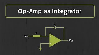
- Basic Design: The Op-Amp is configured within a feedback loop. The error signal is amplified, and the control output adjusts accordingly.
- Key Equation: The control output is expressed by the formula:
\( V_{out} = K_p \times E(t) \)
Where \( V_{out} \) is the control output, \( K_p \) represents the proportional gain, and \( E(t) \) denotes the error signal.
Applications
- In temperature control systems, it maintains the temperature around a setpoint.
- In motor control applications, it regulates the speed ensuring that the motor operates efficiently based on the input error.
Lab Work on Proportional Control Circuits
The lab work encourages students to build a proportional control circuit. They will learn by:
- Using an Op-Amp and related components to construct the circuit.
- Observing the response when varying the proportional gain \( K_p \) and the resulting effect on the output.
Understanding these principles helps develop effective control systems that are paramount in both industrial applications and everyday technologies.
Youtube Videos
Audio Book
Dive deep into the subject with an immersive audiobook experience.
Proportional Control System Overview
Chapter 1 of 5
🔒 Unlock Audio Chapter
Sign up and enroll to access the full audio experience
Chapter Content
In a proportional control system, the output is directly proportional to the input error signal. This type of control is commonly used when the goal is to maintain a system output at a fixed value, with the adjustment being proportional to the error.
Detailed Explanation
A proportional control system adjusts its output based on the difference between a desired setpoint and the actual output. This means if there is a larger error (the difference), the output will be adjusted more significantly to correct that error. This type of control is useful in systems where we want to maintain a specific value, like keeping a room at a certain temperature.
Examples & Analogies
Imagine a thermostat in your home set to 72 degrees Fahrenheit. If the temperature drops to 70 degrees, the thermostat detects a 2-degree error and turns the furnace on to warm the space. Similarly, if the temperature rises to 74 degrees, the system will lower the heat, showing a proportional response to the error.
Design of Proportional Control Circuits
Chapter 2 of 5
🔒 Unlock Audio Chapter
Sign up and enroll to access the full audio experience
Chapter Content
Basic Design:
- The Op-Amp is configured in a feedback loop where the difference between the desired setpoint and the actual output (error signal) is amplified.
- The error signal is processed, and the Op-Amp adjusts the system's control output in proportion to the error.
Detailed Explanation
The design of a proportional control circuit using an Op-Amp typically involves using feedback to measure the difference between what we want (setpoint) and what we currently have (actual output). The Op-Amp takes this difference and amplifies it, which allows for adjustments in the output based on how far off the actual output is from the desired output. Essentially, it's like having a constant check in place to ensure that the system is always striving to reach the target setpoint.
Examples & Analogies
Think of this design as a student preparing for an exam. If they have a target score of 90% but currently have 70%, they identify the difference (20%) and work hard in proportion to that gap, adjusting their study habits based on how far they are from their goal.
Key Equation for Proportional Control
Chapter 3 of 5
🔒 Unlock Audio Chapter
Sign up and enroll to access the full audio experience
Chapter Content
Key Equation:
- The control output is given by:
Vout=Kp×E(t)
Where:
- Vout is the control output,
- Kp is the proportional gain,
- E(t) is the error signal (difference between the setpoint and the measured value).
Detailed Explanation
This equation provides a mathematical framework to understand how the control output (Vout) is computed. The variable E(t) represents the error at any point in time, and Kp is the proportional gain, essentially a scaling factor determining how much the output will change for a given error. For instance, a larger Kp means a stronger response to the error, which can make the system react faster but might also lead to instability if set too high.
Examples & Analogies
Consider driving a car to a specific speed. If you want to go faster (increase your speed) based on a speedometer reading that's below your target, the proportional gain (Kp) represents how aggressively you press on the gas pedal. A small Kp means little pressure on the gas for small speed errors, while a high Kp means you accelerate quickly for even the slightest slow-down, showcasing how control systems adjust based on feedback.
Applications of Proportional Control
Chapter 4 of 5
🔒 Unlock Audio Chapter
Sign up and enroll to access the full audio experience
Chapter Content
Applications:
- Temperature control: Maintaining the temperature of a system at a setpoint.
- Motor control: Regulating the speed of a motor by adjusting the input voltage in proportion to the error between the desired and actual speed.
Detailed Explanation
Proportional control can be applied in various practical scenarios. For temperature control, the system continuously measures the current temperature and adjusts heating or cooling to maintain the desired temperature. Similarly, in motor control, if the motor is spinning slower than desired, the system boosts the voltage proportionately to the deviation until the desired speed is reached. This creates a feedback loop that ensures the system continuously corrects itself.
Examples & Analogies
You can think of this as a cooking process where you need to keep a pot of water boiling. If the temperature drops, you may turn up the heat more if it drops significantly, and just a little if the drop is minimal, ensuring you keep the water at a steady boil without overdoing it.
Lab Work on Proportional Control Circuits
Chapter 5 of 5
🔒 Unlock Audio Chapter
Sign up and enroll to access the full audio experience
Chapter Content
Lab Work on Proportional Control Circuits
- Objective: Build a proportional control circuit to regulate the output based on an error signal.
- Materials:
- Op-Amp (e.g., LM741)
- Resistors for feedback and gain adjustment
- Signal generator and oscilloscope
- Variable power supply or motor
- Procedure:
- Construct a proportional control circuit with an error signal input.
- Apply a known setpoint and measure the output.
- Adjust the proportional gain Kp and observe the system's response to changes in the error signal.
Detailed Explanation
In this lab exercise, students will engage in hands-on experience by building a proportional control circuit. They will use an Op-Amp to manage error signals, apply defined setpoints, and observe the corresponding outputs. By adjusting the Kp gain, students will learn how sensitive the system is to the error, allowing for real-time understanding of control dynamics in a practical way.
Examples & Analogies
Imagine a baking experiment where you adjust how hot your oven is based on the rising of your cake. If it’s rising too quickly, you might reduce the temperature (similar to adjusting Kp down), and if it’s slow to rise, you raise the temperature (adjust Kp up). This process reinforces understanding of how adjustments based on error influence results.
Key Concepts
-
Proportional Control: Adjusts output based on the error signal.
-
Error Signal: The deviation between setpoint and actual output.
-
Feedback Loop: Ensures stability by reverting output to input.
-
Proportional Gain: The factor that scales the error signal.
Examples & Applications
In a temperature control system, a heating element adjusts its output based on the difference from the desired temperature (setpoint).
A motor control system adjusting the input voltage according to the speed discrepancy from what is required.
Memory Aids
Interactive tools to help you remember key concepts
Rhymes
Proportional control, so clear,
Stories
Imagine a heated room that keeps getting too hot.
Memory Tools
Remember Kp = Keep Proportional! Higher Kp means quicker output but might overshoot.
Acronyms
P.A.C.E. = Proportional Adjustments Control Error.
Flash Cards
Glossary
- Operational Amplifier (OpAmp)
An electronic device that amplifies the difference between two input voltages.
- Proportional Control
A control mechanism that adjusts output in direct proportion to the error signal.
- Feedback Loop
A pathway in control systems that allows a portion of the output signal to be returned to the input for automatic adjustments.
- Error Signal (E(t))
The difference between the desired setpoint and the actual output.
- Proportional Gain (Kp)
A constant that amplifies the error signal to produce the control output.
Reference links
Supplementary resources to enhance your learning experience.