
Lab Work on Derivative Control Circuits
Interactive Audio Lesson
Listen to a student-teacher conversation explaining the topic in a relatable way.
Introduction to Derivative Control
🔒 Unlock Audio Lesson
Sign up and enroll to listen to this audio lesson

Today, we're going to explore derivative control circuits. Can anyone tell me what derivative control refers to in a control system?

Isn't it about how the system reacts to changes in errors?
Exactly! Derivative control focuses on the rate of change of the error signal, allowing the system to anticipate future errors. This is vital for applications where quick responses are necessary.

How does this differ from proportional or integral control?
Great question! While proportional control reacts to the current error and integral control addresses accumulated errors over time, derivative control predicts future errors based on their rate of change. Remember, P for Present, I for Integrated, D for Derivative.

Can you summarize why derivative control is useful?
Sure! It's essential for damping oscillations and preventing overshoot within control systems. By combining these strategies, we enhance system stability.
Setting Up the Lab Circuit
🔒 Unlock Audio Lesson
Sign up and enroll to listen to this audio lesson

Now let's talk about the materials we need. Who can list some components we'll be using in our derivative control circuit?
We need an Op-Amp like the LM741, resistors, and capacitors.
That's right! Plus, we’ll need a signal generator and an oscilloscope. Our procedure will start with constructing the circuit to observe its response.

What kind of signals will we use?
Excellent question! We’ll apply signals with known rates of change to see how well our circuit performs. Let's review the setup and the equation we will use.
What happens if the resistor or capacitor values are not correct?
Good insight! Incorrect values may lead to improper differentiation and affect the stability of our system. Always ensure we calculate these accurately.
Observing System Response
🔒 Unlock Audio Lesson
Sign up and enroll to listen to this audio lesson
Let’s start observing the output from our circuits. What should we look for?
We want to see how quickly the output responds to changes in the input error signal.
Correct! We should note if there's a lag or if it overshoots the desired value. Let’s discuss how to measure these responses using our oscilloscope.
How can we quantify if our circuit is performing well?
We can calculate the rise time and overshoot percentage from our data. Remember to take notes on how changes in resistor and capacitor values affect performance.
Will we be able to see how it predicts future errors?
Absolutely! A proper derivative control circuit will adjust its output preemptively as it recognizes changes in error. This characteristic is fundamental to effective predictive control.
Feedback and Adjustments
🔒 Unlock Audio Lesson
Sign up and enroll to listen to this audio lesson
After observing the responses, what adjustments might we consider?
We could change the gain values to see how that affects the output.
Exactly! Adjusting the resistor and capacitor values allows us to fine-tune how sensitive our system is. Who remembers the equation we used?
It's Vout(t) = -RC dE(t)/dt!
Correct! This equation helps us understand the output based on our component values and the rate of change of the error signal.
Can we see an example of what the output looks like on the oscilloscope?
Yes, as we adjust values, let's analyze how the waveform changes, focusing on rise times and settling time for precision in our control system.
Conclusion and Reflection
🔒 Unlock Audio Lesson
Sign up and enroll to listen to this audio lesson
Let's wrap up what we learned today about derivative control circuits. What are the main takeaways?
We learned how to build a circuit that predicts and responds to changes in error signals.
Absolutely! And how is this relevant in real-world applications?
It's important for systems that need to react quickly and smoothly without causing oscillations.
Fantastic insight! Understanding these principles opens the door to designing effective control systems in industries like robotics and automation. Remember the P, I, D control concepts we discussed as they apply here as well.
I’ll remember that derivatives predict errors, like catching a falling ball before it hits the ground!
Great analogy! This understanding is crucial for maintaining stability in systems.
Introduction & Overview
Read summaries of the section's main ideas at different levels of detail.
Quick Overview
Standard
The lab work focuses on constructing a derivative control circuit with an Op-Amp and analyzing its response to rapidly changing error signals. The section emphasizes understanding the operational principles, materials needed, and key objectives for effective learning.
Detailed
Detailed Summary
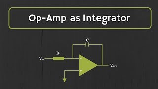
In this section, we delve into the practical aspects of creating derivative control circuits using operational amplifiers (Op-Amps). Derivative control systems are designed to respond to the rate of change of error signals, allowing them to predict future errors and provide appropriate control outputs. The key components include an Op-Amp configured to differentiate the input error signal, and the resulting output is amplified according to the equation:
$$V_{out}(t) = -RC \frac{dE(t)}{dt}$$
where \( V_{out}(t) \) is the output voltage, \( R \) and \( C \) are the resistor and capacitor values, and \( E(t) \) is the error signal. The objective of the lab work involves designing and testing these circuits to examine how effectively they can respond to rapid changes in input. Essential materials needed for this exercise include the Op-Amp (e.g., LM741), resistors, capacitors, a signal generator, and an oscilloscope. By implementing this control system, students gain hands-on experience in measuring how well their derivative control circuits compensate for variations in error.
Youtube Videos
Audio Book
Dive deep into the subject with an immersive audiobook experience.
Objective of the Lab Work
Chapter 1 of 3
🔒 Unlock Audio Chapter
Sign up and enroll to access the full audio experience
Chapter Content
● Objective: Design and test a derivative control circuit for rate-based adjustments.
Detailed Explanation
The primary aim of this lab work is to create a derivative control circuit that can make adjustments based on how quickly the error signal changes. This means you will be focusing on the dynamic response of the system rather than just its steady states. By emphasizing rate-based adjustments, the lab will help you understand the importance of anticipating changes in the system to avoid overshoot and instability.
Examples & Analogies
Think of driving a car: if you only react to the current speed, you might overshoot a turn. However, if you also consider how quickly you're accelerating (the rate of change), you can anticipate the need to slow down before reaching the turn.
Materials Needed
Chapter 2 of 3
🔒 Unlock Audio Chapter
Sign up and enroll to access the full audio experience
Chapter Content
● Materials:
1. Op-Amp (e.g., LM741)
2. Resistors and capacitors for differentiation
3. Signal generator and oscilloscope
Detailed Explanation
For this experiment, you will need specific components: an operational amplifier (like the LM741), which is crucial for creating the derivative control circuit. Resistors and capacitors are also needed for processing the signal—these parts will essentially shape how the circuit responds to input changes. The signal generator will provide the input signal you’ll be testing, and the oscilloscope will be used to visualize the output, allowing you to see how well the circuit reacts to changes in the input.
Examples & Analogies
Imagine baking a cake. You need flour (the Op-Amp), sugar (the resistors), and eggs (the capacitors)—each ingredient is essential for creating your final product. Just like each component in your circuit contributes to how it functions.
Procedure for Building the Circuit
Chapter 3 of 3
🔒 Unlock Audio Chapter
Sign up and enroll to access the full audio experience
Chapter Content
● Procedure:
1. Construct the derivative control circuit using an Op-Amp.
2. Apply a signal with a known rate of change and observe how the output reacts to the rate of change of the error signal.
3. Measure the response to see how well the derivative control can predict and compensate for rapid changes in the error signal.
Detailed Explanation
To start the lab work, you'll first build a derivative control circuit using the operational amplifier. Once it is constructed, you will apply an input signal that varies at a known rate. It’s important to track how this input affects the output. You will need to observe if the circuit can effectively predict and correct for any rapid changes in the error signal. The better it predicts and compensates, the more effective your derivative control circuit is.
Examples & Analogies
Consider a basketball player. If they only react to where the ball currently is (the current error), they may miss it entirely. However, if they also gauge how quickly the ball is moving toward them (the rate of change), they can position themselves to catch it more effectively. Your derivative control circuit is like that player, learning how to anticipate changes.
Key Concepts
-
Derivative Control: A technique that predicts future errors by responding to the rate of change of the error signal.
-
Op-Amp Configuration: The arrangement of components in a circuit that defines its function and response.
-
Error Signal Dynamics: Understanding how changes in input affect system output is critical for effective control.
-
Component Importance: Resistor and capacitor values significantly influence circuit behavior.
Examples & Applications
Example: If the error signal changes rapidly due to a disturbance, a well-designed derivative control circuit will quickly modify its output to stabilize the system.
Example: In a temperature control system, derivative control can prevent overshooting the desired temperature by anticipating changes.
Memory Aids
Interactive tools to help you remember key concepts
Rhymes
In the realm of control so neat,
Stories
Imagine you're driving a car with a high-tech dashboard that predicts when to brake based on how fast the driver presses the gas. This is like derivative control in action, helping you steer clear of sharp turns and stop before the light turns red!
Memory Tools
P, I, D: Present, Integrated, Differentiated — remember the control types by their action on error.
Acronyms
DRIVE
Derivative Responds Instantly to Variations in Error.
Flash Cards
Glossary
- Derivative Control
A control strategy that reacts to the rate of change of the error signal to predict future errors.
- OpAmp
An operational amplifier, a type of voltage amplifier used in various electronic circuits, particularly in control systems.
- Error Signal
The difference between the desired setpoint and the actual output in a control system.
- Differentiator Configuration
A setup in which an Op-Amp is used to produce an output proportional to the rate of change of the input signal.
Reference links
Supplementary resources to enhance your learning experience.