
Lab Work on Proportional Control Circuits
Interactive Audio Lesson
Listen to a student-teacher conversation explaining the topic in a relatable way.
Introduction to Proportional Control Circuits
🔒 Unlock Audio Lesson
Sign up and enroll to listen to this audio lesson

Today, we will explore how proportional control circuits work. Who can tell me what proportional control means?

Isn't it where the output changes in direct proportion to the input error?
Exactly! The output adjusts based on the magnitude of the error. We often express this relationship with the formula Vout = Kp × E(t). Let's remember this with the acronym 'K.E.E.' for 'Kp, Error, Output.'

So, how does that apply to our lab work?
Great question! In our lab, we'll construct a circuit where the Op-Amp amplifies the error signal to regulate outputs. This gives you hands-on experience with the concept.
Materials Needed for the Lab
🔒 Unlock Audio Lesson
Sign up and enroll to listen to this audio lesson

Let's discuss the materials we'll need. Can anyone mention what components we need for our proportional control circuit?

I think we need an Op-Amp, some resistors, and maybe a power supply?
Correct! We'll be using an Op-Amp like the LM741, resistors for feedback, and a signal generator. Now, what will the oscilloscope help us with?

It will let us measure the output and see how it changes!
Exactly! You'll observe how the output reflects the changes in the error signal.
Constructing the Circuit
🔒 Unlock Audio Lesson
Sign up and enroll to listen to this audio lesson
Now let's move on to constructing the circuit. Who can summarize the steps we need to follow?
We first connect the Op-Amp in a feedback loop with our error signal input.
Correct! Then, we apply a known setpoint. What do you think we'll do next?
Measure the output and adjust the gain?
Yes! Adjusting Kp allows us to observe changes in response. This is a crucial step in understanding how the adjustment impacts the output.
Observing the Responses
🔒 Unlock Audio Lesson
Sign up and enroll to listen to this audio lesson
Now that we’ve built our circuit, let’s talk about the responses we should expect. Why is adjusting Kp important?
Because it affects how quickly the system responds to the error!
Exactly! A higher Kp means a more aggressive response. We’re testing this principle today.
What happens if Kp is too high?
Great question! If Kp is too high, it may lead to overshooting the target value. We'll investigate this during our experiment!
Lab Summary
🔒 Unlock Audio Lesson
Sign up and enroll to listen to this audio lesson
To wrap up, what have we learned about proportional control today?
We learned how to regulate outputs using an error signal and how the proportional gain affects system response.
Exactly! Remember the key formula Vout = Kp × E(t) and the implications of adjusting Kp. These insights are vital in various control applications!
Introduction & Overview
Read summaries of the section's main ideas at different levels of detail.
Quick Overview
Standard
This section outlines the goal of constructing a proportional control circuit with necessary materials and a step-by-step procedure. It emphasizes the importance of adjusting the proportional gain to observe system response to error signals.
Detailed
Lab Work on Proportional Control Circuits
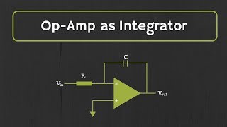
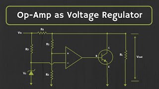
This section describes the practical component of learning about proportional control circuits, focusing on the construction and testing of an operational amplifier (Op-Amp) based circuit that regulates outputs based on an error signal. The objective is to build a functional proportional control circuit using specific materials: an Op-Amp (such as the LM741), resistors, a signal generator, an oscilloscope, and a variable power supply or motor.
Key Steps in the Procedure:
- Circuit Construction: Students will learn to build the circuit by integrating an error signal input that reflects the difference between the setpoint and actual output.
- Applying Setpoints: They will apply known setpoints and measure the output to ensure the circuit functions correctly.
- Adjusting Proportional Gain: Finally, students will adjust the proportional gain (Kp) and note how the output responds to changes in the error signal, deepening their understanding of system behavior in control applications.
Youtube Videos

Audio Book
Dive deep into the subject with an immersive audiobook experience.
Objective of the Lab Work
Chapter 1 of 3
🔒 Unlock Audio Chapter
Sign up and enroll to access the full audio experience
Chapter Content
● Objective: Build a proportional control circuit to regulate the output based on an error signal.
Detailed Explanation
The goal of this lab work is to create a proportional control circuit. This circuit will automatically adjust its output in response to an error signal, which is the difference between the desired and actual output. The main idea is to ensure that the output remains as close as possible to a predefined setpoint by proportionally reacting to any errors.
Examples & Analogies
Think of this like a thermostat in your home. If the temperature drops below a setpoint, the thermostat turns on the heating. If it gets too warm, it turns off the heating. The adjustments (output from the thermostat) are proportional to the temperature difference (the error).
Required Materials
Chapter 2 of 3
🔒 Unlock Audio Chapter
Sign up and enroll to access the full audio experience
Chapter Content
● Materials:
1. Op-Amp (e.g., LM741)
2. Resistors for feedback and gain adjustment
3. Signal generator and oscilloscope
4. Variable power supply or motor
Detailed Explanation
To build the proportional control circuit, you'll need several materials: an operational amplifier (like the LM741), which is the core component for amplifying the error signal; resistors that will help adjust feedback and gain; a signal generator and oscilloscope to provide input signals and visualize the output; and either a variable power supply or a motor to represent the system being controlled.
Examples & Analogies
Imagine you're a chef adjusting the flavor of a sauce. You'll need various ingredients (like the Op-Amp and resistors) to achieve the perfect taste, just as you'd need a thermometer and taste tests to adjust the seasoning until it’s just right.
Procedure Steps
Chapter 3 of 3
🔒 Unlock Audio Chapter
Sign up and enroll to access the full audio experience
Chapter Content
● Procedure:
1. Construct a proportional control circuit with an error signal input.
2. Apply a known setpoint and measure the output.
3. Adjust the proportional gain KpK_p and observe the system's response to changes in the error signal.
Detailed Explanation
The procedure consists of three key steps. First, you will build the proportional control circuit, incorporating the error signal input. Next, you'll set a specific setpoint (the target value you want) and then actually measure the output of the circuit to see how close it gets to this setpoint. Lastly, you'll vary the proportional gain (Kp), which determines how strongly the output responds to the error signal. By doing this, you can observe how changing this parameter affects the system's performance—whether the system stabilizes quickly or takes too long.
Examples & Analogies
Think of it like tuning a bike. When you first set the handlebars (your circuit), you want to ensure they're at the right angle (the setpoint). As you ride, you feel if they need adjusting or not (measuring the output). Depending on how sensitive your brakes are (adjusting Kp), you might react quicker or slower to changes in your path (the error signal).
Key Concepts
-
Proportional Control: A mechanism where the output is directly proportional to the error.
-
Error Signal: The difference between the desired output setpoint and the actual output values.
-
Proportional Gain (Kp): A constant used in proportional control that affects the sensitivity of the control system's response.
Examples & Applications
In a temperature control system, if the actual temperature is 20°C and the desired setpoint is 25°C, then the error signal is 5°C. A proportional control circuit would adjust the heating output based on this error.
In motor speed control, if the desired speed is 1500 RPM, but the motor is running at 1200 RPM, the proportional control adjusts the input voltage to increase the motor speed proportionally to the difference.
Memory Aids
Interactive tools to help you remember key concepts
Rhymes
If there's an error, don't you fret, control it proportionally, make it set!
Stories
Imagine a baker adjusting the oven based on how far the bread is from perfect; just like him, our circuit responds to the error.
Memory Tools
E.P.O. = Error, Proportional, Output helps us remember the elements in proportional control.
Acronyms
P.E.R.F.E.C.T = Proportional, Error, Regulated, Feedback, Error Control Together.
Flash Cards
Glossary
- Operational Amplifier (OpAmp)
A high-gain electronic voltage amplifier with differential inputs and a single-ended output, used in control circuits.
- Proportional Control
A control mechanism that produces an output that is directly proportional to the error signal.
- Error Signal
The difference between the desired setpoint and the actual output of the system.
- Proportional Gain (Kp)
A constant that determines the ratio of the output response to the error signal in a proportional control system.
Reference links
Supplementary resources to enhance your learning experience.