
Op-Amps in Control Circuits
Interactive Audio Lesson
Listen to a student-teacher conversation explaining the topic in a relatable way.
Introduction to Op-Amps in Control Circuits
🔒 Unlock Audio Lesson
Sign up and enroll to listen to this audio lesson

Welcome to our discussion on operational amplifiers, or Op-Amps, in control circuits. Can anyone tell me what an Op-Amp does?

Isn’t it used to amplify voltage signals?
Exactly! Op-Amps amplify signals, but in control circuits, they do much more. They help maintain the stability of systems and ensure accurate feedback. What do you think this stability means in practical applications?

Does it mean keeping a system's output steady, like in a thermostat?
Yes, precisely! A thermostat controls temperature by adjusting output based on error signals. This leads us to our first key term: stability.

What kind of control methods do we have?
Great question! We have proportional, integral, derivative, and PID control methods. Let's explore these!
Proportional Control Circuits
🔒 Unlock Audio Lesson
Sign up and enroll to listen to this audio lesson

In proportional control, the output is adjusted based on the error signal. Can someone explain what a feedback loop is?

It's where the output of a system is fed back into the input to control the system?
Correct! In our equations, we have V_out = K_p × E(t). What does K_p represent?
It’s the proportional gain that determines how responsive the system is to errors!
Right! Applications include temperature regulation and motor speed control. Let's think: How would increasing K_p affect system response?
It would make the system respond faster to changes, right?
Exactly! But too high might cause instability. That's why tuning is crucial!
Integral Control Circuits
🔒 Unlock Audio Lesson
Sign up and enroll to listen to this audio lesson
Now, let’s discuss integral control. Recall that it accumulates error over time. Can anyone relate this to a real-life scenario?
Like how a car might keep correcting its position over time?
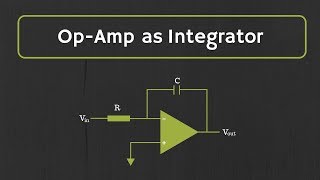
Exactly! It helps eliminate steady-state errors. The equation is V_out(t) = (1/RC) ∫E(t) dt. What does this integral signify?
It shows that the output increases or decreases based on accumulated error.
Spot on! Consider applications like precise position control: Why is integral control important in this context?
It ensures that the system stays at the desired position accurately without drift.
Great! Remember, the integral control is like adding layers of correction to ensure stability.
Derivative Control Circuits
🔒 Unlock Audio Lesson
Sign up and enroll to listen to this audio lesson
Next up is derivative control, which predicts future errors based on the rate of change. Why might it be beneficial?
It helps to correct problems before they escalate!
Exactly! The equation for derivative control is V_out(t) = -RC dE(t)/dt. Can someone explain what this derivative represents?
It represents how fast the error is changing over time, allowing the system to respond quickly.
Perfect! This is particularly useful in dynamics to reduce overshoot. What kind of systems would benefit from this control?
Systems like drones or robots that need immediate adjustments to maintain stability.
Right! Let’s keep this predictive approach in mind as we move into PID control.
PID Control Circuits
🔒 Unlock Audio Lesson
Sign up and enroll to listen to this audio lesson
Now we combine all three control types into PID control. Can anyone remind us of each component's role?
Proportional deals with present error, integral eliminates steady-state error, and derivative predicts future error.
Exactly! The PID controller takes inputs from all three to create a robust output. What systems might benefit from such a comprehensive approach?
Industrial processes and robotics, for precise control of different parameters.
Absolutely! Each component contributes uniquely. Remember, tuning of these parameters is vital for the desired performance without instability.
How do you usually tune these parameters?
That's a great question! Techniques like Ziegler-Nichols allow us to find the right balance. Let’s summarize: Op-Amps are essential for achieving controlled stability in many applications.
Introduction & Overview
Read summaries of the section's main ideas at different levels of detail.
Quick Overview
Standard
Op-Amps are essential components in control circuits, where they enhance system stability and output regulation through various control strategies. This section explains the design and application of proportional, integral, derivative, and PID control circuits, highlighting their unique functions and significance in practical systems like temperature and motor control.
Detailed
Op-Amps in Control Circuits
Operational amplifiers (Op-Amps) serve a vital role in control circuits, ensuring system stability and precise output regulation. In diverse applications—including temperature and motor control—Op-Amps facilitate control strategies such as proportional, integral, and derivative control, culminating in the widely used PID (Proportional-Integral-Derivative) control.
Control Strategies
-
Proportional Control: The output directly relates to the error signal, adjusting proportionately to maintain a setpoint.
- Design: Configured in a feedback loop to amplify the error signal.
- Use Cases: Suitable for applications like temperature regulation.
-
Integral Control: The output is based on the accumulated error over time, effectively eliminating steady-state errors in dynamic systems.
- Design: Utilizes an integrator configuration to process the error signal.
- Use Cases: Employed in systems where maintaining precise position is critical.
-
Derivative Control: Responds to the rate of change of the error, enabling predictive adjustments before issues become pronounced.
- Design: Differentiator configuration amplifies changes in the error signal.
- Use Cases: Ideal for damping oscillations and ensuring quality response dynamics.
-
PID Control: Combines proportional, integral, and derivative components, refining feedback for superior control across various systems.
- Design: Typically includes three Op-Amps for a comprehensive control output.
- Use Cases: Widely used in industrial automation and robotics for enhanced performance.
Conclusion
Incorporating these control strategies lays a foundation for the complex feedback systems essential in various engineering and automation applications, emphasizing the significance of Op-Amps in modern control systems.
Youtube Videos
Audio Book
Dive deep into the subject with an immersive audiobook experience.
Introduction to Op-Amps in Control Circuits
Chapter 1 of 4
🔒 Unlock Audio Chapter
Sign up and enroll to access the full audio experience
Chapter Content
Operational amplifiers (Op-Amps) are widely used in control circuits, where they play a critical role in maintaining system stability, regulating outputs, and ensuring accurate feedback. In control systems, Op-Amps are employed in various configurations to implement different control strategies, such as proportional, integral, and derivative control, as well as PID control (Proportional-Integral-Derivative).
This chapter covers the design and analysis of Op-Amp-based control circuits, providing a deeper understanding of their application in systems such as temperature control, motor control, and automated systems.
Detailed Explanation
This section introduces operational amplifiers (Op-Amps) as essential components in control circuits. An Op-Amp is a type of electronic amplifier that can amplify weak signals and is utilized in various configurations. Control circuits are vital for ensuring systems function smoothly and maintain stability by adjusting outputs based on feedback. Op-Amps are used in various control strategies, including:
1. Proportional Control: Adjusting output based on the direct error between the setpoint and actual output.
2. Integral Control: Adjusting output based on the accumulated past errors.
3. Derivative Control: Adjusting output based on how quickly the error is changing.
4. PID Control: A combination of all three strategies for enhanced performance.
The chapter aims to provide insights into designing and analyzing these circuits for real-world applications such as temperature control and motor management.
Examples & Analogies
Consider a thermostat in your home. It uses an Op-Amp-based control circuit to maintain the desired temperature. If the room temperature drops below the setpoint, the Op-Amp acts like a smart assistant that detects this drop (the error) and signals the heater to turn on to increase the temperature back to the setpoint. This feedback loop ensures your environment stays comfortable.
Op-Amp-based Proportional Control Circuits
Chapter 2 of 4
🔒 Unlock Audio Chapter
Sign up and enroll to access the full audio experience
Chapter Content
In a proportional control system, the output is directly proportional to the input error signal. This type of control is commonly used when the goal is to maintain a system output at a fixed value, with the adjustment being proportional to the error.
Detailed Explanation
Proportional control is a straightforward method where the output of the control system is directly proportional to the error signal. This means that the greater the difference between the desired output (setpoint) and the actual output, the larger the corrective action taken by the system. For example, if you want a room temperature of 70°F but it’s currently 60°F, the output (like the heater turning on) will be significant enough to correct this 10°F error. The proportional factor, known as the gain (Kp), dictates how strongly the system reacts to the error.
Examples & Analogies
Think of a car's cruise control system. If you set the speed at 60 mph but the car slows down to 50 mph, the cruise control will increase the throttle (the output) to bring the speed back up to 60 mph. If the speed drops more, the system increases the throttle even more, maintaining the desired speed accurately.
Design of Proportional Control Circuits
Chapter 3 of 4
🔒 Unlock Audio Chapter
Sign up and enroll to access the full audio experience
Chapter Content
● Basic Design:
○ The Op-Amp is configured in a feedback loop where the difference between the desired setpoint and the actual output (error signal) is amplified.
○ The error signal is processed, and the Op-Amp adjusts the system's control output in proportion to the error.
● Key Equation:
○ The control output is given by:
Vout=Kp×E(t)
Where:
■ Vout is the control output,
■ Kp is the proportional gain,
■ E(t) is the error signal (difference between the setpoint and the measured value).
● Applications:
○ Temperature control: Maintaining the temperature of a system at a setpoint.
○ Motor control: Regulating the speed of a motor by adjusting the input voltage in proportion to the error between the desired and actual speed.
Detailed Explanation
To design a proportional control circuit, we start by setting up an Op-Amp within a feedback loop. The feedback loop compares the desired output with the actual output to find the error. This error signal gets amplified by the Op-Amp, which then adjusts the system output proportionally. The basic equation guiding this relationship is Vout = Kp × E(t), where Kp represents how sensitive the system is to changes in error.
The applications of such circuits are vast; for example, in temperature control, the system keeps adjusting until it maintains the desired temperature. In motor control, if the observed speed is less than the target, the circuit ramps up the voltage sent to the motor accordingly.
Examples & Analogies
Imagine a simple water tank system where you want to maintain a specific water level. The Op-Amp compares the desired level with the current level (the error) and adjusts a valve to let more water in when the level is too low. If the water level is just below where it should be, the valve opens a little (small error), but if it's much lower, the valve opens wide (large error) to fill the tank faster.
Lab Work on Proportional Control Circuits
Chapter 4 of 4
🔒 Unlock Audio Chapter
Sign up and enroll to access the full audio experience
Chapter Content
● Objective: Build a proportional control circuit to regulate the output based on an error signal.
● Materials:
1. Op-Amp (e.g., LM741)
2. Resistors for feedback and gain adjustment
3. Signal generator and oscilloscope
4. Variable power supply or motor
● Procedure:
1. Construct a proportional control circuit with an error signal input.
2. Apply a known setpoint and measure the output.
3. Adjust the proportional gain Kp and observe the system's response to changes in the error signal.
Detailed Explanation
In the lab, the primary objective is to create a working proportional control circuit. To do this, you will need to gather materials like an Op-Amp and resistors. The circuit construction involves connecting the Op-Amp to form a feedback loop, allowing you to input an error signal. After constructing the circuit, you will apply a known setpoint, which is the desired output, and see how the circuit reacts. By manipulating the proportional gain (Kp), you can explore how sensitive the system is to the error and assess how it adjusts the output accordingly.
Examples & Analogies
This lab exercise is like tuning an audio system. Imagine you have a volume knob (the gain) that adjusts how loud the music plays (the output). If the music is too low (error), turning the knob increases the volume proportionally, making it louder until it reaches your desired listening level.
Key Concepts
-
Operational Amplifier (Op-Amp): A critical component in control circuits for amplifying input signals and managing feedback.
-
Control Strategies: The methods employed (proportional, integral, derivative, PID) to stabilize and manage systems effectively.
-
Stability: The ability of a control system to maintain desired output across variations in the input.
Examples & Applications
In temperature control applications, an Op-Amp monitors the difference between a setpoint and measured temperature, adjusting heating or cooling as needed.
In motor speed control, the Op-Amp adjusts voltage to regulate speed by comparing desired speed with actual speed.
Memory Aids
Interactive tools to help you remember key concepts
Rhymes
Proportional leads to quick control, while integral fixes the goal's hold, derivatives keep change in sight, together PID keeps it all right!
Stories
Imagine a thermostat—proportional control adjusts the heat based on how cold it gets. If it stays cold longer (integral), it cranks up heating more. And if suddenly it becomes freezing (derivative), it prepares for a warm-up before the chill sets in!
Memory Tools
Remember PID as 'Please Integrate Derivatives' for a smooth control experience.
Acronyms
PID stands for Proportional, Integral, Derivative, the three main types of control functionalities.
Flash Cards
Glossary
- OpAmp
An operational amplifier, a high-gain voltage amplifier used in control circuits.
- Proportional Control
A control strategy where the output is directly proportional to the error signal.
- Integral Control
A control strategy that integrates the error over time, eliminating steady-state errors.
- Derivative Control
A control strategy that responds to the rate of change of the error signal.
- PID Control
A control strategy that combines proportional, integral, and derivative controls.
- Feedback Loop
A system structure where the output is fed back into the input for control.
Reference links
Supplementary resources to enhance your learning experience.