
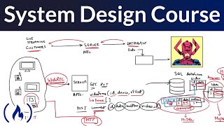
System Block Diagram
Interactive Audio Lesson
Listen to a student-teacher conversation explaining the topic in a relatable way.
Purpose of System Block Diagrams
🔒 Unlock Audio Lesson
Sign up and enroll to listen to this audio lesson

Today, we are discussing the system block diagram. Can anyone explain why we use block diagrams in system architecture?

I think they are used to show the interactions between different system components.

It helps to simplify complex systems and makes them easier to understand.
Great points! The block diagram indeed simplifies complex architectures and provides a clear visual representation of how components interact. Remember the acronym 'SIMPLE' - it stands for **S**implification, **I**ntegration, **M**anagement, **P**lanning, **L**ayout, and **E**ngineering collaboration. Let's keep that in mind!

So, it can help in planning and validating system designs?
Exactly! By visualizing interactions, we can easily spot potential issues before they arise. Let’s delve deeper into the components of a block diagram.
Components of a Block Diagram
🔒 Unlock Audio Lesson
Sign up and enroll to listen to this audio lesson

What do you think are the key components included in a system block diagram?

I believe it includes the processing units and memory, right?
And it should also show interfaces for communication between components!
Correct! The main components are the processing units, memory types, interfaces, sensors, and power management elements. Each plays a critical role in the overall architecture. Let’s reinforce this: **PIMS** - **P**rocessing units, **I**nterfaces, **M**emory, **S**ensors.
If we remember those components, we can easily understand the whole system!
Absolutely! By understanding these components, we can better grasp how they cooperate to achieve system objectives.
Advantages of Block Diagrams
🔒 Unlock Audio Lesson
Sign up and enroll to listen to this audio lesson
Let's discuss the advantages of using block diagrams. Why do you think they are beneficial?
They help with clarity and organization in the design process.
Yeah, and I guess they make it easier for teams to communicate about designs.
Perfect observations! Block diagrams provide clarity, standardization, and collaboration opportunities. A mnemonic to remember these benefits is **CLEAR** - **C**larity, **L**ayout, **E**ffectiveness, **A**ccuracy, and **R**eporting.
That’s easy to remember! This really helps in collaboration too.
Exactly! Clear communication is vital in ensuring successful design outcomes.
Introduction & Overview
Read summaries of the section's main ideas at different levels of detail.
Quick Overview
Standard
This section focuses on the system block diagram as a critical documentation tool in hardware systems architecture. It highlights how the diagram offers a comprehensive view of system components, their roles, and interconnections, assisting engineers in understanding and refining system designs.
Detailed
System Block Diagram
The system block diagram is a crucial component in documenting the architecture of hardware systems. It provides a high-level overview that illustrates how different components interact within the system. The diagram typically includes various subsystems, their functions, and the relationships between these components, making it easier for engineers to visualize the overall design. Here are the main aspects covered in this section:
Purpose of System Block Diagrams
- High-Level Overview: The block diagram presents a simplified view of the system, making complex architectures more understandable.
- Component Interaction: It denotes how different components communicate and work together, allowing for better planning and integration.
Components of the Diagram
- Processing Units: Illustrates the microcontrollers or processors that drive the system.
- Memory: Shows data storage components essential for system functionality.
- Interfaces: Represents the communication protocols used for component interaction.
- Sensors/Actuators: Displays any physical interaction with the environment.
- Power Management: Details on how the system is powered and managed.
- Mechanical Housing: Incorporates aspects like form factor and thermal management.
Advantages of Using Block Diagrams
- Simplification of Complex Systems: They help in breaking down complex systems into more manageable parts.
- Standardization: Provides a consistent way to document designs across various teams.
- Facilitation of Collaboration: Helps teams communicate effectively regarding system requirements and design considerations.
In summary, the system block diagram is invaluable for visualizing the architecture of hardware systems, enabling engineers to design, validate, and refine complex systems before implementation.
Youtube Videos

Audio Book
Dive deep into the subject with an immersive audiobook experience.
High-level System View
Chapter 1 of 5
🔒 Unlock Audio Chapter
Sign up and enroll to access the full audio experience
Chapter Content
System Block Diagram High-level system view
Detailed Explanation
A system block diagram provides a visual representation of a hardware system's architecture. It highlights the main components and how they interact or communicate with each other at a glance. This diagram simplifies complex relationships and brings clarity to system design, allowing engineers to understand the system's structure before diving into detailed designs.
Examples & Analogies
Think of a system block diagram like a map of a city. Just as a map gives you an overview of the streets, buildings, and parks, a block diagram gives you an overview of the system components and their connections, helping you navigate through the design process.
Purpose of a System Block Diagram
Chapter 2 of 5
🔒 Unlock Audio Chapter
Sign up and enroll to access the full audio experience
Chapter Content
Interface Control Document (ICD) Defines signal and communication interfaces
Detailed Explanation
The purpose of a system block diagram includes defining the interactions between components. This is further supported by the Interface Control Document (ICD), which specifies the types of signals and communication protocols used in the system. Understanding these interfaces is crucial for ensuring that different components can effectively communicate and work together to achieve the intended functionality.
Examples & Analogies
Imagine a group project where each team member has specific roles and communicates through defined channels, like emails or meetings. The ICD is like the guidelines for communication, just as the roles clarify who does what. This ensures that even though there are multiple contributors, the project comes together smoothly.
Documentation and Communication
Chapter 3 of 5
🔒 Unlock Audio Chapter
Sign up and enroll to access the full audio experience
Chapter Content
Architecture Description Document (ADD) Comprehensive architectural rationale
Detailed Explanation
The System Block Diagram is part of essential documentation in hardware design, especially included in the Architecture Description Document (ADD). This document encompasses a detailed rationale for the selected architecture, explaining why particular decisions were made concerning performance, cost, and complexity. Documentation like this aids in communication among engineering teams and ensures that everyone involved understands the reason behind the design choices.
Examples & Analogies
Consider writing a recipe when you cook. The recipe not only tells you what ingredients to use but also explains why you need them and how to combine them effectively. Similarly, the ADD communicates the 'recipe' of the system architecture, enabling others to follow or adapt the design.
Validation Through Functional Models
Chapter 4 of 5
🔒 Unlock Audio Chapter
Sign up and enroll to access the full audio experience
Chapter Content
Functional Models/Simulations Validate expected behaviors
Detailed Explanation
After constructing a system block diagram, engineers often create functional models or simulations. These tools help validate the expected behavior of the system based on the architecture laid out in the block diagram. This validation stage is crucial because it allows designers to identify potential issues and make necessary adjustments before committing to a physical prototype.
Examples & Analogies
Imagine testing a new video game before its release. Developers create simulations to see how different game mechanics work together and fix any bugs. Similarly, functional models allow engineers to simulate and refine their hardware designs, ensuring that everything works correctly before the real build.
Version Control of Models and Diagrams
Chapter 5 of 5
🔒 Unlock Audio Chapter
Sign up and enroll to access the full audio experience
Chapter Content
Versioned Models and Diagrams Maintain traceability and revisions
Detailed Explanation
Maintaining versioned models and diagrams is key to tracing the development process of a hardware system. It ensures that all changes are documented, and different iterations can be referenced. This ongoing version control helps prevent confusion as projects evolve and ensures that the engineering teams can return to previous designs if needed.
Examples & Analogies
Think of version control like saving different drafts of a paper. Each time you tweak your work or want to try a new idea, you save it with a new version. If the new version doesn’t work out, you can revert back to an earlier draft. Similarly, versioned models in a hardware project allow engineers to track changes and, if necessary, roll back to a previous version.
Key Concepts
-
System Block Diagram: A visual representation that details system components and their relationships.
-
Processing Unit: Key component responsible for executing instructions.
-
Memory: Stores data and code essential for processing tasks.
-
Interfaces: Protocols that enable communication between different system parts.
-
Power Management: Mechanisms that ensure efficient energy use in the system.
Examples & Applications
A system block diagram for a temperature-monitoring IoT device that includes a microcontroller, temperature sensor, Wi-Fi module, and battery management system.
The diagram showing how different subsystems like power management, processing unit, and communication interfaces interact in an embedded control system.
Memory Aids
Interactive tools to help you remember key concepts
Rhymes
Block diagrams show where parts might, make connections clear and out of sight.
Stories
Imagine a baker (the processing unit) whipping up cake batter (memory) with various utensils (interfaces), working together to create a perfect cake (the system).
Memory Tools
Remember PIMS - Processing units, Interfaces, Memory, Sensors.
Acronyms
SIMPLE
**S**implification
**I**ntegration
**M**anagement
**P**lanning
**L**ayout
**E**ngineering collaboration.
Flash Cards
Glossary
- System Block Diagram
A high-level representation of a system showing its components and their interactions.
- Processing Unit
The part of the system capable of processing data, such as a microcontroller or microprocessor.
- Memory
Components that store data and instructions, including RAM, ROM, and flash memory.
- Interface
Communication channels that facilitate interaction between components.
- Sensors/Actuators
Devices that allow the system to interact with the physical world.
- Power Management
Hardware focused on regulating and distributing power within the system.
Reference links
Supplementary resources to enhance your learning experience.