
Design of RF Filters
Interactive Audio Lesson
Listen to a student-teacher conversation explaining the topic in a relatable way.
Introduction to RF Filters
🔒 Unlock Audio Lesson
Sign up and enroll to listen to this audio lesson

Today we’re discussing RF filters, which play a key role in signal processing. Can anyone tell me the primary function of a filter?

To allow certain frequencies to pass while blocking others?
Exactly! We have different types of filters such as low-pass, high-pass, and band-pass filters. Let's focus on how we can design these filters.

What do we use for designing a low-pass filter?
For a low-pass filter, a common design uses a series inductor and a parallel capacitor. The cutoff frequency is one of the critical parameters. Does anyone remember the formula for it?

Isn’t it related to L and C?
That's right! The formula is \( f_c = \frac{1}{2\pi \sqrt{LC}} \). This helps us determine at which frequency the filter starts to attenuate higher frequencies.

And how does it work in practical applications?
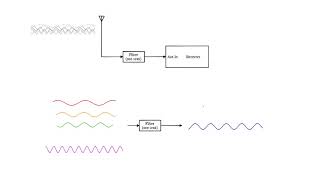
Great question! In communication systems, for instance, low-pass filters remove unwanted high-frequency noise to ensure signal clarity. Now, let’s recap: RF filters control frequency passage through design principles based on cutoff frequency.
High-Pass Filter Design
🔒 Unlock Audio Lesson
Sign up and enroll to listen to this audio lesson

Now let’s talk about high-pass filters. Does anyone know the components used in their design?
I think it’s a capacitor in series and an inductor in parallel?
That's correct! The same formula for cutoff frequency also applies: \( f_c = \frac{1}{2\pi \sqrt{LC}} \). How do you think this is useful?
Maybe to block low frequencies in audio applications?
Exactly, that’s a common use! High-pass filters are often utilized in audio processing to allow higher frequencies while blocking lower ones. Great job!
Can a high-pass filter be used in communication too?
Absolutely! High-pass filters help isolate certain signal channels by filtering out low-frequency noise, enhancing the communication quality. Let’s summarize the key points about high-pass filters before we move on.
Band-Pass Filter Design
🔒 Unlock Audio Lesson
Sign up and enroll to listen to this audio lesson
Next, we’ll discuss band-pass filters. What's unique about their design?
Is it that they're made by combining low-pass and high-pass filters?
Yes! A band-pass filter allows a specific range of frequencies to pass through. Can anyone tell me how we determine the center frequency for these filters?
There's a formula that involves both L and C, right?
Correct! The center frequency is calculated using the formulas for the components in both filters: \( f_0 = \frac{1}{2 \pi \sqrt{L_1 C_1}} = \frac{1}{2 \pi \sqrt{L_2 C_2}} \).
What’s the application of band-pass filters in real life?
In communication systems, band-pass filters isolate desired frequencies, allowing for clearer signal processing without unwanted interference. Recap: band-pass filters combine frequency selection, critical for efficient signal transmission.
Introduction & Overview
Read summaries of the section's main ideas at different levels of detail.
Quick Overview
Standard
In this section, we explore the design principles of RF filters, including calculations for cutoff frequencies and the configuration of various filter types such as low-pass, high-pass, and band-pass filters. Understanding these concepts is crucial for effective signal processing in RF systems.
Detailed
Design of RF Filters
RF filters are essential components in the design of RF systems, enabling the selection and rejection of signals based on frequency. This section focuses on the methods for designing common types of filters: low-pass, high-pass, and band-pass. Each filter type has specific configurations and cutoff frequency calculations.
Low-Pass Filter Design
The simplest configuration of a low-pass filter consists of a series inductor and a parallel capacitor. The cutoff frequency is determined by the inductance (
L) and capacitance (
C) used in the design. The formula for calculating the cutoff frequency is:
\[ f_c = \frac{1}{2 \pi \sqrt{L C}} \]
Where:
- \( f_c \) is the cutoff frequency,
- \( L \) is the inductance,
- \( C \) is the capacitance.
High-Pass Filter Design
A high-pass filter can be constructed using a series capacitor combined with a parallel inductor. Notably, the same formula for cutoff frequency applies:
\[ f_c = \frac{1}{2 \pi \sqrt{L C}} \]
Band-Pass Filter Design
A band-pass filter is typically established by integrating a low-pass filter with a high-pass filter. The center frequency of the band-pass filter, which is crucial for isolating desired signals, is given by two equations that relate the components in each filter section:
\[ f_0 = \frac{1}{2 \pi \sqrt{L_1 C_1}} = \frac{1}{2 \pi \sqrt{L_2 C_2}} \]
In essence, understanding how these filters operate and are designed is fundamental for ensuring optimal performance in RF applications.
Youtube Videos
Audio Book
Dive deep into the subject with an immersive audiobook experience.
Low-Pass Filter Design
Chapter 1 of 3
🔒 Unlock Audio Chapter
Sign up and enroll to access the full audio experience
Chapter Content
The simplest low-pass filter can be made using a series inductor and a parallel capacitor. The cutoff frequency for an LC low-pass filter is given by:
fc=12πLC
Where fc is the cutoff frequency, L is the inductance, and C is the capacitance.
Detailed Explanation
A low-pass filter is designed to let low frequencies pass through while attenuating higher frequencies. The simplest form can be created with an inductor placed in series and a capacitor in parallel. The cutoff frequency, which is the point at which the filter begins to reduce the signal strength, is determined by the values of the inductor and capacitor used. The formula provides a relationship between the inductor and capacitor, showing how their values affect the cutoff frequency.
Examples & Analogies
Think of a low-pass filter as a gatekeeper at a concert who allows only certain fans (lower frequencies) in while keeping out rowdy ones (higher frequencies). The inductor and capacitor work together like the gate and the rules the gatekeeper uses to decide who gets in.
High-Pass Filter Design
Chapter 2 of 3
🔒 Unlock Audio Chapter
Sign up and enroll to access the full audio experience
Chapter Content
A high-pass filter can be designed using a series capacitor and a parallel inductor. The cutoff frequency is the same as for the low-pass filter:
fc=12πLC
Detailed Explanation
A high-pass filter is analogous to the low-pass filter but works in the opposite way. It allows high frequencies to pass through while attenuating lower frequencies. This is achieved by connecting a capacitor in series and an inductor in parallel. The cutoff frequency remains the same as with low-pass filters, indicating the transition point where the filter starts to reduce signal strength at lower frequencies.
Examples & Analogies
Imagine a high-pass filter as a filter that only lets in the high notes of a musical instrument and blocks out the lower, booming sounds. The capacitor and inductor are like a music selector that ensures only the preferred sounds (higher frequencies) pass through.
Band-Pass Filter Design
Chapter 3 of 3
🔒 Unlock Audio Chapter
Sign up and enroll to access the full audio experience
Chapter Content
A band-pass filter can be made by combining a low-pass filter and a high-pass filter in series. The center frequency of the band-pass filter is determined by:
f0=12πL1C1=12πL2C2
Detailed Explanation
A band-pass filter allows a specific range of frequencies to pass while blocking both lower and higher frequencies. It is created by connecting a low-pass filter and a high-pass filter in series. The center frequency, which defines the middle of this frequency range, is calculated using the values of the inductors and capacitors from both the low-pass and high-pass sections. This design ensures that only signals within a particular bandwidth are allowed through.
Examples & Analogies
Think of a band-pass filter as a special radio tuner that allows you to listen to a certain radio station (specific frequency range) while cutting out all the static and noise (unwanted frequencies). The filters work together like dials on the tuner, ensuring you only hear what you want to hear.
Key Concepts
-
Low-Pass Filter: A filter that allows signals below a certain frequency and attenuates higher frequencies.
-
High-Pass Filter: A filter that allows signals above a certain frequency and attenuates lower frequencies.
-
Band-Pass Filter: A combination filter that allows a specific range of frequencies to pass.
-
Cutoff Frequency: The frequency at which the filter begins to attenuate the signal.
-
Quality Factor (Q): Indicates how selective a filter is regarding frequencies.
Examples & Applications
A low-pass filter might be used in audio systems to eliminate high-frequency noise while allowing music frequencies to pass through.
A band-pass filter could be utilized in a radio receiver to isolate a specific frequency band, like FM radio signals, from a wide range of frequencies.
Memory Aids
Interactive tools to help you remember key concepts
Rhymes
Low frequencies run free, while highs get cut, that's the low-pass nut.
Stories
Imagine a gatekeeper at a signal pass, who only lets certain sounds through while blocking out the rest. This is how filters work to manage audio signals.
Memory Tools
For filters: LHS for Low-Pass, HHS for High-Pass, and BPS for Band-Pass.
Acronyms
LPF for Low-Pass Filter, HPF for High-Pass Filter, and BPF for Band-Pass Filter.
Flash Cards
Glossary
- LowPass Filter
A circuit that allows signals below a certain frequency to pass while attenuating higher frequencies.
- HighPass Filter
A circuit that allows signals above a certain frequency to pass while attenuating lower frequencies.
- BandPass Filter
A filter that allows a specific range of frequencies to pass while attenuating frequencies outside that range.
- Cutoff Frequency
The frequency at which the output power of a filter begins to attenuate the input signal.
- Quality Factor (Q)
A measure of the selectivity of a filter; higher Q factors indicate narrower bandwidth.
Reference links
Supplementary resources to enhance your learning experience.