
Lab Work on RF Filters
Interactive Audio Lesson
Listen to a student-teacher conversation explaining the topic in a relatable way.
Introduction to RF Filters
🔒 Unlock Audio Lesson
Sign up and enroll to listen to this audio lesson

Today, we’re focusing on RF filters. Can anyone tell me what an RF filter is?

Isn’t it something that only allows certain frequencies to pass through?
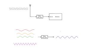
Exactly! RF filters are used to allow signals within specific frequency ranges and reject others. They play a vital role in communication systems.

What are the types of RF filters?
Good question! The main types are low-pass, high-pass, band-pass, and band-stop filters. Can anyone give me an example of where we might use a band-pass filter?

In a radio receiver, right? To isolate certain channels?
Correct! It helps isolate the desired frequency band for better clarity.
Before we start our lab, let's summarize: RF filters manage frequency signals, and there are different types for different applications.
Components of RF Band-Pass Filter
🔒 Unlock Audio Lesson
Sign up and enroll to listen to this audio lesson

Next, we’ll discuss the components needed for a band-pass filter. Can anyone tell me what components we might use?

We need inductors and capacitors, right?
Exactly! We combine inductors and capacitors to create the desired frequency response. The center frequency is defined by how we arrange these components.
What is the formula for the center frequency?
Great question! The center frequency (f0) is calculated using the formula: f0 = 1 / (2 * π * √(L1 * C1)).
What does this mean for our design?
We need to choose appropriate values for L and C to get the desired frequency. Let’s remember: careful selection affects performance!
Lab Procedure for Building the Band-Pass Filter
🔒 Unlock Audio Lesson
Sign up and enroll to listen to this audio lesson
Now let’s go through the procedure for lab work. What is our first step?
We need to design the filter for a specific center frequency, right?
Absolutely! After that, we’ll build the filter circuit with the components. Does anyone remember what comes next?
We apply a range of frequencies with the signal generator!
Yes! We’ll measure the output signal and observe frequency response using the oscilloscope. This helps us see the filter’s effectiveness!
And what do we look for in the measurements?
We’ll check if the filter passes the right frequencies while attenuating others. Remember: observation and adjustments are key!
Analysis and Observations
🔒 Unlock Audio Lesson
Sign up and enroll to listen to this audio lesson
Once we've built and tested our filter, what will we analyze?
The output signal’s amplitude and the frequencies that get through?
Correct! We’ll also discuss what happens if we change the inductor or capacitor values. Who can guess how that affects our filter?
If we change L or C, the cutoff frequencies will shift?
Exactly! Tuning the filter is crucial for performance. It’s all about balancing the design and goals.
This helps us understand practical implications of our designs!
Indeed! Remember that practical analysis in labs solidifies theoretical knowledge.
Introduction & Overview
Read summaries of the section's main ideas at different levels of detail.
Quick Overview
Standard
The lab work on RF filters involves creating a band-pass filter using inductors and capacitors, understanding the significance of center frequency and bandwidth, and measuring the frequency response using an oscilloscope.
Detailed
Lab Work on RF Filters
This section presents practical laboratory work focused on RF filters, specifically the design and analysis of an RF band-pass filter. A band-pass filter is crucial in communication systems as it allows a specific range of frequencies to pass while attenuating others. The objectives include designing the filter for a desired center frequency and bandwidth, constructing the filter circuit with inductors and capacitors, applying various frequency signals using a signal generator, and observing the output frequency response through an oscilloscope. Understanding the components and their arrangement is essential for successful filter implementation in RF applications.
Youtube Videos
Audio Book
Dive deep into the subject with an immersive audiobook experience.
Objective of the Lab Work
Chapter 1 of 3
🔒 Unlock Audio Chapter
Sign up and enroll to access the full audio experience
Chapter Content
● Objective: Design and analyze an RF band-pass filter to pass a specific range of frequencies.
Detailed Explanation
In this lab work, the main goal is to design and analyze an RF band-pass filter. A band-pass filter is a device that allows signals within a certain frequency range to pass through while blocking signals that are outside this range. This objective is essential in many communication applications where you want to isolate signals of interest from unwanted noise or interference.
Examples & Analogies
Think of a band-pass filter like a bouncer at a club. The bouncer lets in guests that meet the specific criteria (like wearing the right color shirt) and denies entry to those who don't, just as the band-pass filter allows only certain frequencies through while keeping others out.
Materials Required
Chapter 2 of 3
🔒 Unlock Audio Chapter
Sign up and enroll to access the full audio experience
Chapter Content
● Materials:
1. Inductors and capacitors
2. Signal generator and oscilloscope
3. Resistors for impedance matching
Detailed Explanation
To conduct this lab work, you'll need several materials: inductors and capacitors form the fundamental components of the band-pass filter; the signal generator allows you to create signals of different frequencies to test the filter; the oscilloscope enables you to visualize and analyze the output signal; and resistors are used for impedance matching to ensure the filter works efficiently with the rest of the circuit.
Examples & Analogies
Imagine you are baking a cake, you need specific ingredients (like flour and sugar) to create the cake (the filter). Here, inductors, capacitors, and resistors are those ingredients, while the signal generator and oscilloscope are your kitchen tools that help you prepare and check the final result.
Lab Procedure Steps
Chapter 3 of 3
🔒 Unlock Audio Chapter
Sign up and enroll to access the full audio experience
Chapter Content
● Procedure:
1. Design the filter for a specific center frequency and bandwidth.
2. Build the filter circuit and apply a range of frequencies using a signal generator.
3. Measure the output signal and observe the frequency response using an oscilloscope.
Detailed Explanation
The procedure involves three main steps. First, you need to design the filter to specify the frequency range you want it to pass through (this is the center frequency and bandwidth). Next, you will physically build the filter circuit using the materials listed. Then you apply different frequencies from the signal generator to see how the filter responds. Finally, you'll measure the output signal with the oscilloscope to analyze the filter's performance and verify that it only allows the desired frequencies while rejecting others.
Examples & Analogies
Think of this procedure like creating a music playlist. First, you decide which songs (frequencies) will be included in your playlist (the design step). Next, you arrange them into a playlist (the circuit building). Then, you play the playlist and listen to see if the music sounds good (measuring output with the oscilloscope) to ensure only the songs you want to hear are playing.
Key Concepts
-
Band-Pass Filter: A device allowing signals within a certain frequency range to pass while attenuating others.
-
Center Frequency: The optimal frequency around which the band-pass filter is designed.
-
Inductors and Capacitors: Fundamental components used to construct filters.
-
Frequency Response: The output signal characteristics in relation to input frequencies.
Examples & Applications
A band-pass filter designed for a radio receiver allows only the desired station's frequency to pass, filtering out others.
In audio processing, a band-pass filter can isolate musical notes within a specific frequency range, enhancing audio clarity.
Memory Aids
Interactive tools to help you remember key concepts
Rhymes
A band-pass filter lets some frequencies in, / While others are blocked, it's where signals begin.
Stories
Imagine a musician tuning their instrument to a perfect pitch. The band-pass filter helps isolate that perfect sound from the noise around it.
Memory Tools
BAP: Band-pass allows specifically the frequencies you want.
Acronyms
FRA
Frequency Response Affects (understanding how filter components react).
Flash Cards
Glossary
- BandPass Filter
A filter that allows frequencies within a specific range to pass while rejecting frequencies outside that range.
- Center Frequency
The frequency at which the response of a band-pass filter is maximized.
- Inductor
A passive electrical component that stores energy in a magnetic field; often used in filter circuits.
- Capacitor
A passive electrical component that stores energy in an electric field; typically used in filter circuits.
Reference links
Supplementary resources to enhance your learning experience.