
RF Filters
Interactive Audio Lesson
Listen to a student-teacher conversation explaining the topic in a relatable way.
Introduction to RF Filters
🔒 Unlock Audio Lesson
Sign up and enroll to listen to this audio lesson

Today, we are diving into RF filters, a critical component in communication systems. Can anyone share what they think is the main purpose of an RF filter?

I think it's to allow certain frequencies to pass while blocking others.
Exactly, Student_1! Filters are essential for isolating signals. Now, there are different types of RF filters. What do you think these types could be?

Are they like low-pass and high-pass filters?
Yes, great job! We have low-pass, high-pass, band-pass, and band-stop filters. Each serves a specific function. Let's remember the acronym 'HBLB' for 'High-Band, Low-Band' to keep these types in mind!

What does a band-stop filter do?
A band-stop filter, or notch filter, eliminates a specific frequency range. Excellent question, Student_3! It’s used when interference occurs at specific frequencies.
In summary, RF filters play a crucial role by allowing or blocking frequencies. Remember the acronym 'HBLB' for types of filters!
RF Filter Design Considerations
🔒 Unlock Audio Lesson
Sign up and enroll to listen to this audio lesson

Now let's discuss the design considerations for RF filters. What do you think is the most important factor when designing a filter?

Maybe the cutoff frequency?
Correct, Student_4! The cutoff frequency dictates which frequencies will be filtered out. What other design aspects should we consider?
What about the quality factor? I recall it affects selectivity.
Exactly! A higher Q factor results in sharper filtering, but it can introduce more loss. This reminds me of the saying: 'Quality Over Quantity' helps you remember to prioritize selectivity!
And impedance matching must be considered too, right?
Absolutely! Impedance matching is essential for efficient power transfer. Remember, efficient design means considering all these factors!
So to recap, the important factors in filter design are cutoff frequency, quality factor, and impedance matching.
Designing Different Types of Filters
🔒 Unlock Audio Lesson
Sign up and enroll to listen to this audio lesson
Next, let's look at how to design these filters. Starting with low-pass and high-pass filters, how do you think we can create them?
Could we use capacitors and inductors?
"Exactly! A low-pass filter can be made using a series inductor and a parallel capacitor. The cutoff frequency for an LC low-pass filter is calculated as:
Practical Applications of RF Filters
🔒 Unlock Audio Lesson
Sign up and enroll to listen to this audio lesson
Finally, let's discuss the practical applications of RF filters. Where do you think filters are predominantly used?
In communication systems like radios!
Exactly! They're essential in isolating desired signals in radios and other communication devices. Can anyone think of a specific example?
How about in Wi-Fi routers?
Great example! Wi-Fi routers use RF filters to manage their signal transmissions. Remember, RF filters are critical across various technologies like radar and audio processing as well.
To summarize, RF filters are crucial in communication systems, and we see their applications across many areas, including Wi-Fi and radar systems!
Introduction & Overview
Read summaries of the section's main ideas at different levels of detail.
Quick Overview
Standard
This section explores the different types of RF filters, including low-pass, high-pass, band-pass, and band-stop filters. It discusses their design considerations, such as cutoff frequency, quality factor, and impedance matching, which are essential for optimizing filter performance in various RF applications.
Detailed
RF Filters
RF filters are critical components in radio frequency (RF) systems, allowing specific signals to pass through while blocking others. This functionality is vital in applications such as communication systems, where clean signal transmission is required. The main types of RF filters include:
1. Types of RF Filters
- Low-Pass Filter (LPF): Allows frequencies below a certain cutoff frequency to pass through while attenuating higher frequencies. Commonly used to eliminate high-frequency noise.
- High-Pass Filter (HPF): Allows frequencies above a specific cutoff frequency to pass, attenuating lower frequencies. Useful in audio processing and signal conditioning.
- Band-Pass Filter (BPF): Permits a specific range of frequencies to pass, thus attenuating frequencies outside this range. Widely used in communication systems to isolate signals.
- Band-Stop Filter (BSF): Attenuates a specific band of frequencies, allowing others to pass. Effective for eliminating interference at known frequencies.
2. RF Filter Design Considerations
When designing RF filters, several key factors must be taken into account:
- Cutoff Frequency: Defines the point at which the filter starts to attenuate signals.
- Quality Factor (Q): Reflects the filter's selectivity; higher Q indicates a narrower bandwidth and sharper filtering.
- Impedance Matching: Ensures efficient power transfer and minimizes signal reflection, often using matching networks.
- Filter Order: Determines roll-off steepness and cutoff sharpness; higher-order filters provide better performance but with increased complexity.
3. Design of RF Filters
Low-Pass Filter Design
The simplest low-pass filter can be created using a series inductor and a parallel capacitor. The cutoff frequency is calculated as:
$$ f_c = \frac{1}{2 \pi \sqrt{LC}} $$
High-Pass Filter Design
Constructed with a series capacitor and a parallel inductor, the cutoff frequency aligns with the low-pass filter definition:
$$ f_c = \frac{1}{2 \pi \sqrt{LC}} $$
Band-Pass Filter Design
Combining low-pass and high-pass filters in series results in a band-pass filter, where the center frequency is defined by:
$$ f_0 = \frac{1}{2 \pi \sqrt{L_1 C_1}} = \frac{1}{2 \pi \sqrt{L_2 C_2}} $$
4. Practical Applications
RF filters play essential roles in various communication systems, ensuring the selection and isolation of desired signals, ultimately improving system performance.
Youtube Videos
Audio Book
Dive deep into the subject with an immersive audiobook experience.
Introduction to RF Filters
Chapter 1 of 5
🔒 Unlock Audio Chapter
Sign up and enroll to access the full audio experience
Chapter Content
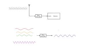
RF filters are used to pass signals within a specific frequency range and reject others. Filters are essential in communication systems to separate signals, remove noise, and select the desired channel.
Detailed Explanation
RF filters are specialized circuits designed to manage which frequencies of an electrical signal are allowed to pass through and which are blocked. This is vital in communication systems where clarity of the signal is essential; filters help to eliminate unwanted noise and ensure the right signals reach their destination. Essentially, they are like bouncers at a club, allowing only preferred guests (specific signals) inside while turning away others (unwanted signals).
Examples & Analogies
Imagine you're at a party with loud music playing. You can only hear your friend talking if you focus on their voice and block out the noise from the music. Similarly, RF filters allow certain frequencies to enter while blocking out others. The filters help maintain a clear conversation by removing distractions.
Types of RF Filters
Chapter 2 of 5
🔒 Unlock Audio Chapter
Sign up and enroll to access the full audio experience
Chapter Content
Low-Pass Filter (LPF):
A low-pass filter allows frequencies below a certain cutoff frequency to pass through while attenuating higher frequencies. It is commonly used to remove high-frequency noise from signals.
High-Pass Filter (HPF):
A high-pass filter allows frequencies above a certain cutoff frequency to pass and attenuates lower frequencies. It is used in applications such as audio processing and signal conditioning.
Band-Pass Filter (BPF):
A band-pass filter allows a specific range of frequencies to pass and attenuates frequencies outside this range. It is commonly used in communication systems to isolate signals of interest, such as in RF tuners.
Band-Stop Filter (BSF):
A band-stop filter, also known as a notch filter, attenuates a specific range of frequencies and allows frequencies outside this range to pass. It is useful for eliminating unwanted interference at a specific frequency.
Detailed Explanation
There are four main types of RF filters:
1. Low-Pass Filters (LPF) - These filters allow signals below a certain frequency to pass, eliminating high-frequency noise. They’re commonly used in audio applications to clean up sound signals.
2. High-Pass Filters (HPF) - Opposite to LPFs, HPFs let higher frequencies through while blocking lower ones. They help in scenarios like audio processing where bass sounds need to be diminished.
3. Band-Pass Filters (BPF) - BPFs let through a certain range of frequencies while blocking those outside this range. They're essential in radios and communication systems for focusing on specific signal bands.
4. Band-Stop Filters (BSF) - These filters block a specific range of frequencies while allowing others to pass, effectively removing unwanted signals (like noise) at a certain frequency.
Understanding these types of filters is crucial for ensuring that only the desired signals are processed in various electronic applications.
Examples & Analogies
Think of RF filters as a set of gates at a concert venue:
- Low-Pass Filters are like a gate for people under a certain height, allowing them in while sending taller individuals away. This way, the event remains manageable and enjoyable for everyone.
- High-Pass Filters function like a security line that only allows people over a certain height, screening out those who do not meet that height standard.
- Band-Pass Filters can be likened to VIP tickets—only certain ticket holders can enter specific areas.
- Band-Stop Filters are comparable to restrictions on certain behaviors, like not allowing drinks in specific areas to ensure cleanliness. Each type of filter ensures the environment (or signal) remains as desired, without unwanted disruptions.
RF Filter Design Considerations
Chapter 3 of 5
🔒 Unlock Audio Chapter
Sign up and enroll to access the full audio experience
Chapter Content
Cutoff Frequency:
The cutoff frequency of a filter determines the point where the filter begins to attenuate the signal. The filter should be designed to pass signals within the desired frequency range and reject unwanted frequencies.
Quality Factor (Q):
The Q factor defines the selectivity of the filter. A higher Q factor results in a narrower bandwidth, providing sharper filtering. However, high-Q filters may introduce more loss at the cutoff frequency.
Impedance Matching:
Filters need to be impedance-matched to the rest of the system to ensure efficient power transfer and minimize reflection. Impedance matching networks are often used in conjunction with filters.
Filter Order:
The order of the filter determines the steepness of the roll-off and the sharpness of the cutoff. Higher-order filters provide better selectivity but may require more components.
Detailed Explanation
Several critical factors must be considered during RF filter design:
1. Cutoff Frequency - This is the frequency at which the filter starts to reduce signal strength. It should be precisely defined to ensure that desired frequencies pass through while unwanted frequencies are blocked.
2. Quality Factor (Q) - The Q factor impacts how sharply the filter reacts to frequencies. A higher Q provides better filtering but can lead to losses at the cutoff frequency. Think of it as a more refined scalpel versus a blunt knife—more precision but potentially less versatility.
3. Impedance Matching - This ensures that the signal can move efficiently through the system without losing energy. Poor impedance matching can result in signal reflections that degrade performance. It’s akin to ensuring a standard-sized plug fits the socket connected to your device; mismatches lead to problems.
4. Filter Order - This relates to the complexity of your circuit. A higher order means a steeper drop-off from passed to blocked frequencies. It’s like a city’s zoning laws; more restrictions can lead to better planning but often require more regulations (or components). Balancing these factors is essential for effective filter performance.
Examples & Analogies
Think of designing an RF filter like planning a restaurant menu:
- Cutoff Frequency is similar to establishing a price point—food items below that price are included in the menu while those above are declined. This ensures diners only see what fits their budget.
- Quality Factor (Q) relates to the complexity of dishes offered. A more sophisticated menu usually means more expertise and tighter control over ingredients, akin to how a higher Q filter is more selective.
- Impedance Matching is like harmonizing your cuisine with the customers’ expectations—when they're in sync, the dining experience is pleasant, just as matched impedances lead to efficient signal transmission.
- Filter Order resembles the number of courses on a menu. A longer menu provides a wider variety (better selectivity) but may lead to higher chef workload, similar to the additional components needed for more complex designs.
Aligning these factors creates a successful filter design, just like a well-received menu.
Design of RF Filters
Chapter 4 of 5
🔒 Unlock Audio Chapter
Sign up and enroll to access the full audio experience
Chapter Content
Low-Pass Filter Design:
The simplest low-pass filter can be made using a series inductor and a parallel capacitor. The cutoff frequency for an LC low-pass filter is given by:
fc=1/(2π√(LC))
Where fc is the cutoff frequency, L is the inductance, and C is the capacitance.
High-Pass Filter Design:
A high-pass filter can be designed using a series capacitor and a parallel inductor. The cutoff frequency is the same as for the low-pass filter:
fc=1/(2π√(LC))
Band-Pass Filter Design:
A band-pass filter can be made by combining a low-pass filter and a high-pass filter in series. The center frequency of the band-pass filter is determined by:
f0=1/(2π√(L1C1)) = 1/(2π√(L2C2))
Detailed Explanation
The design process for RF filters can be understood through three primary types:
1. Low-Pass Filter Design - The most basic version uses an inductor in series with a load and a capacitor in parallel. The formula for determining the cutoff frequency involves both the inductance and capacitance values. Understanding this relationship allows engineers to design effective low-pass filters.
2. High-Pass Filter Design - Similar to the low-pass design, but with the configuration flipped. Here, the filter allows higher frequencies to pass while blocking lower ones, following the same cutoff frequency formula.
3. Band-Pass Filter Design - This is essentially a combination of both low-pass and high-pass filters working together. The calculation for the center frequency of a band-pass filter must ensure that signals crucial for proper communication smoothly pass through while blocking others.
An understanding of these formulas and how they apply in circuits is the foundation of effective RF filter design.
Examples & Analogies
Consider the design of RF filters as like preparing different coffee brews:
- Low-Pass Filter design is akin to brewing a dark roast coffee—allowing only deep, rich flavors to shine through while heavier, bitter notes from the roast are kept at bay.
- High-Pass Filter design parallels brewing a light, refreshing beverage where it's essential to enhance brightness while eliminating overly heavy tastes.
- Band-Pass Filter design is like crafting a blended coffee drink, combining the best elements of dark and light roasts to create a uniquely enjoyable flavor. Just as each coffee type requires precise measures of beans (inductance and capacitance), ensuring the right mix creates the ideal coffee experience, so does RF filter design ensure the right signal makes it through.
Lab Work on RF Filters
Chapter 5 of 5
🔒 Unlock Audio Chapter
Sign up and enroll to access the full audio experience
Chapter Content
Objective:
Design and analyze an RF band-pass filter to pass a specific range of frequencies.
Materials:
- Inductors and capacitors
- Signal generator and oscilloscope
- Resistors for impedance matching
Procedure:
- Design the filter for a specific center frequency and bandwidth.
- Build the filter circuit and apply a range of frequencies using a signal generator.
- Measure the output signal and observe the frequency response using an oscilloscope.
Detailed Explanation
In a laboratory setup for RF filters, students engage in hands-on activities.
1. Objective - The primary goal is to design a band-pass filter that specifically allows a selected frequency range.
2. Materials Needed - Inductors and capacitors form the core components of the filter, while a signal generator provides the test signals and an oscilloscope helps visualize performance.
3. Procedure Steps -
- First, students will draft a design outlining what the filter should do concerning desired frequencies.
- Next, the physical assembly occurs where components are connected in their designed configuration.
- The final step is testing by applying a range of frequencies and measuring how effectively the filter performs using the oscilloscope, providing invaluable feedback on the design's practicality.
Such exercises are crucial for reinforcing theoretical knowledge through practical application.
Examples & Analogies
Think of this lab work as preparing a dish through trial and error:
1. Objective corresponds to determining the ultimate flavor profile (what you want the dish to taste like).
2. Materials represent the ingredients necessary to create that flavor.
3. Procedure- Designing the dish, combining ingredients, and then taste-testing to check if the flavors meld as intended, refining the recipe as needed just like testing the filter output. The combination of design, assembly, and iterative testing ensures that the final output hits the mark, just like achieving the perfect culinary dish.
Key Concepts
-
RF Filters: Components that allow certain frequencies to pass while blocking others.
-
Low-Pass Filter: Allows frequencies below a cutoff to pass.
-
High-Pass Filter: Allows frequencies above a cutoff to pass.
-
Band-Pass Filter: Allows a specific range of frequencies to pass.
-
Impedance Matching: Ensuring consistent impedance for optimal signal flow.
Examples & Applications
A low-pass filter is used in audio processing to remove high-frequency noise from the sound signals.
A band-stop filter is implemented in medical imaging systems to eliminate interference frequencies during scans.
Memory Aids
Interactive tools to help you remember key concepts
Rhymes
Low and high, they filter the sound, / Frequencies low, high are drowned.
Stories
Imagine a bouncer at a club: low-pass allows all the cool guests in, but high-pass only lets in those dressed for success.
Memory Tools
To remember filter types: LBHBS - Low, Band-pass, High, Band-stop.
Acronyms
HIGH (for High-pass), LOW (for Low-pass), BAND (for Band-pass), STOP (for Band-stop) filters.
Flash Cards
Glossary
- Cutoff Frequency
The frequency at which a filter begins to attenuate signals.
- Quality Factor (Q)
A measure of the selectivity of a filter; higher Q indicates a narrower bandwidth.
- Impedance Matching
The process of ensuring that the input and output of the filter match the impedance of the system to minimize signal loss.
- LowPass Filter (LPF)
A filter that allows frequencies below a certain cutoff frequency to pass through while attenuating higher frequencies.
- HighPass Filter (HPF)
A filter that allows frequencies above a certain cutoff frequency to pass while attenuating lower frequencies.
- BandPass Filter (BPF)
A filter that allows a specific range of frequencies to pass and attenuates frequencies outside this range.
- BandStop Filter (BSF)
A filter that attenuates a specific range of frequencies while allowing others to pass.
Reference links
Supplementary resources to enhance your learning experience.