
RF Amplifiers and Filters
Interactive Audio Lesson
Listen to a student-teacher conversation explaining the topic in a relatable way.
Introduction to RF Amplifiers
🔒 Unlock Audio Lesson
Sign up and enroll to listen to this audio lesson

Welcome, everyone! Today, we're diving into RF amplifiers. Can anyone tell me what an RF amplifier does?

It amplifies radio frequency signals.
Exactly! RF amplifiers boost weak signals and are essential in communication and broadcasting. Now, who remembers the primary challenges in designing RF amplifiers?

Maintaining high gain while minimizing noise and distortion?
That's correct! We often use the mnemonic 'GND'—Gain, Noise, Distortion—to remember these challenges. Can anyone summarize the different configurations of RF amplifiers?

Common-emitter, common-collector, and common-base amplifiers.
Good job! Let's remember their main characteristics and applications as we move forward.
RF Amplifier Configurations
🔒 Unlock Audio Lesson
Sign up and enroll to listen to this audio lesson

Let's discuss specific configurations. Who can explain what a common-emitter amplifier does?

It provides high voltage gain and is used in low-power RF circuits.
Yes! The gain equation for the common-emitter amplifier is \( A_v = -\frac{R_C}{r_e} \). What does this equation tell us?
It indicates that the voltage gain depends on the collector resistance and internal emitter resistance.
Exactly! Now, how does the common-collector configuration differ?
It provides a low output impedance and high input impedance, typically with unity gain.
Well stated. Remember the acronym 'ICH' for Input, Collector, and High impedance. Let's summarize these configurations.
Design Considerations for RF Amplifiers
🔒 Unlock Audio Lesson
Sign up and enroll to listen to this audio lesson
What are the key design considerations for RF amplifiers?
Gain, bandwidth, noise figure, and impedance matching.
Excellent! Can anyone elaborate on why noise figure is crucial?
A low noise figure is essential for maintaining the quality of the amplified signal.
Absolutely! Remember this with 'NQ', Noise Quality. Stability is also a concern. Why?
It ensures consistent performance across frequency ranges without oscillations.
Exactly! You've all done great! Understanding these considerations helps in designing effective RF amplifiers.
Introduction to RF Filters
🔒 Unlock Audio Lesson
Sign up and enroll to listen to this audio lesson
Now, let's shift topics to RF Filters. Why do we need filters in RF systems?
To pass specific frequencies and block others, right?
Exactly! Filters help eliminate noise and interference. Can anyone name the types of RF filters?
Low-pass, high-pass, band-pass, and band-stop filters.
Well done! Let's remember them with 'LHBS': Low, High, Band-pass, and Stop filters. Which filter is most commonly used in communication systems?
Band-pass filters! They isolate the signals.
Perfect answer! Understanding filter types is vital for effective RF communication.
Design Considerations for RF Filters
🔒 Unlock Audio Lesson
Sign up and enroll to listen to this audio lesson
What are some design considerations when creating RF filters?
Cutoff frequency and quality factor.
Correct! The cutoff frequency is crucial. Can someone explain the Quality Factor (Q)?
It determines how sharply a filter can isolate frequencies. A higher Q means a narrower bandwidth.
Exactly! Let’s remember Q with 'Quality Sharp'. Now, what about impedance matching?
It ensures efficient power transfer and reduces signal reflection.
Great! Summarizing, understanding these considerations allows for the effective design and implementation of RF filters!
Introduction & Overview
Read summaries of the section's main ideas at different levels of detail.
Quick Overview
Standard
RF amplifiers and filters are essential components in RF and HF circuits, vital for amplifying weak signals and selecting frequency ranges. This section outlines basic configurations of RF amplifiers, their design challenges, types of filters, and practical applications of these components in various systems.
Detailed
RF Amplifiers and Filters
In the realm of RF (Radio Frequency) and HF (High Frequency) circuits, RF amplifiers and filters serve as foundational elements, critical in enhancing and purifying signals. RF amplifiers amplify weak signals and must be designed to minimize distortion and noise. This section explores:
RF Amplifiers
RF amplifiers operate typically from a few kHz to several GHz, aimed at providing high gain while addressing challenges such as noise, distortions, and unwanted reflections.
Basic Configurations:
- Common-Emitter (CE) Amplifier: Provides high voltage gain, moderate impedance, and is popular in low-power applications.
- Gain Equation: \( A_v = -\frac{R_C}{r_e} \)
- Common-Collector (CC) Amplifier: Known as an emitter follower, buffers signals with low output impedance and high input impedance.
- Gain Equation: \( A_v = 1 - \frac{R_L}{R_E + r_e} \)
- Common-Base (CB) Amplifier: Used in high-frequency scenarios, this configuration offers high voltage gain but low input impedance.
- Gain Equation: Similar to CE: \( A_v = -\frac{R_C}{r_e} \)
Design Considerations:
Key design parameters include gain, bandwidth, noise figure, impedance matching, linearity, and stability, all crucial to the effective functioning of RF amplifiers.
RF Filters
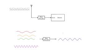
RF filters are used to permit certain frequency bands while rejecting others.
Types of RF Filters:
- Low-Pass Filter (LPF): Allows low frequencies to pass, useful for noise removal.
- High-Pass Filter (HPF): Permits high frequencies, useful in audio processing.
- Band-Pass Filter (BPF): Passes a particular band, widely used in communication to isolate signals.
- Band-Stop Filter (BSF): Rejects a specific frequency band, mitigating interference.
Design Considerations:
Elements such as cutoff frequency, quality factor (Q), impedance matching, and filter order are pivotal in filter design.
Practical Applications
RF amplifiers are employed in communication systems, signal processing, and radar systems. Filters focus on signal isolation and interference removal.
The section concludes with the essence of understanding RF amplifier and filter performance as vital to successful RF system operation.
Youtube Videos
Audio Book
Dive deep into the subject with an immersive audiobook experience.
Introduction to RF Amplifiers and Filters
Chapter 1 of 12
🔒 Unlock Audio Chapter
Sign up and enroll to access the full audio experience
Chapter Content
RF amplifiers and filters are two of the most critical components in RF (Radio Frequency) and HF (High Frequency) circuits. RF amplifiers are used to amplify weak RF signals, while filters are used to select or reject specific frequency ranges. Together, they form the core of many RF systems, including communication, broadcasting, radar, and measurement systems. This chapter covers the basic configurations of RF amplifiers and the design and analysis of RF filters, focusing on both the theory and practical considerations for effective circuit performance.
Detailed Explanation
RF amplifiers and filters play essential roles in the functioning of Radio Frequency (RF) and High Frequency (HF) circuits. RF amplifiers boost weak radio signals, making them strong enough for processing. Filters, on the other hand, allow certain frequencies to pass while blocking others, ensuring that only the desired signals are processed. This combination is vital in many systems, like radio communications and radar systems, where clarity and accuracy of signals are paramount. The section sets the stage to explore how these components work individually and collectively.
Examples & Analogies
Think of RF amplifiers as speakers in a concert that make quiet sounds loud enough for everyone to hear, while filters serve as gatekeepers, deciding which sounds (or frequencies) get to pass through and be amplified. Just like a concert may include many noises, only some are worth amplifying!
RF Amplifiers Overview
Chapter 2 of 12
🔒 Unlock Audio Chapter
Sign up and enroll to access the full audio experience
Chapter Content
RF amplifiers are designed to amplify signals at high frequencies, typically from a few kHz to several GHz. The primary challenge in RF amplifier design is to maintain high gain while minimizing distortion, noise, and unwanted signal reflections.
Detailed Explanation
RF amplifiers are specialized devices intended to amplify electrical signals at high frequencies, which is crucial for effective signal processing. One must ensure that while increasing the strength of these signals (gain), unwanted effects like distortion and noise do not compromise the quality. Distortion can alter the original signal, leading to errors in communication, while noise can render the signal unreadable. Therefore, effective RF amplifier design focuses heavily on achieving a balance between high gain and low distortion.
Examples & Analogies
Consider a public speaker trying to talk in a loud, noisy environment. They need a good microphone (like an RF amplifier) that not only amplifies their voice but also filters out background noise, ensuring their message is clear. If the speaker is too distorted, the audience struggles to understand them, just like in an RF system with poor amplifier design!
Basic Configurations of RF Amplifiers
Chapter 3 of 12
🔒 Unlock Audio Chapter
Sign up and enroll to access the full audio experience
Chapter Content
Common-Emitter (CE) Amplifier:
The common-emitter amplifier is a basic configuration used in both low- and high-frequency applications. It provides voltage gain and is widely used in low-power RF circuits.
- Characteristics:
- High voltage gain.
- Moderate input and output impedance.
- Gain Equation:
Av=−RCreA_v = -\frac{R_C}{r_e}
Where RCR_C is the collector resistance, and rer_e is the internal emitter resistance.
Common-Collector (CC) Amplifier:
This configuration is known as the emitter follower and is used for impedance matching and providing a low output impedance. The gain is typically less than 1, but it is used to buffer signals.
- Characteristics:
- Low voltage gain (unity gain).
- High current gain.
- High input impedance and low output impedance.
- Gain Equation:
Av=1−RLRE+reA_v = 1 - \frac{R_{L}}{R_E + r_e}
Where RLR_L is the load resistance, and RER_E is the emitter resistance.
Common-Base (CB) Amplifier:
The common-base amplifier has a high voltage gain but very low input impedance. It is used primarily in high-frequency applications where impedance matching is required, especially for low-noise amplification.
- Characteristics:
- High voltage gain.
- Low input impedance.
- Gain Equation:
Av=−RCreA_v = -\frac{R_C}{r_e}
Similar to the common-emitter amplifier.
Detailed Explanation
RF amplifiers can be arranged in several configurations, each suited to different applications. The common-emitter amplifier is popular for general amplification needs due to its ability to provide significant voltage gain. It’s quite versatile but requires specific impedance settings. The common-collector amplifier, also called an emitter follower, is tailored for situations where impedance matching is crucial, resulting in good current gain and low output impedance. Lastly, the common-base amplifier excels at high-frequency applications but has low input impedance, making it suitable when low-noise amplification is necessary. Each configuration has its own benefits and equations for calculating gain, illustrating their unique design principles.
Examples & Analogies
Think of these configurations like different types of amplifiers in a concert setup. The common-emitter is like a powerful microphone that can project voice very well. The common-collector acts like a personal speaker that helps someone hear without distortion but doesn’t make voices louder. Conversely, the common-base amplifier can be viewed as an effective soundboard, which improves sound quality but doesn't take as many inputs!
RF Amplifier Design Considerations
Chapter 4 of 12
🔒 Unlock Audio Chapter
Sign up and enroll to access the full audio experience
Chapter Content
The primary design considerations for RF amplifiers include:
- Gain: High gain is a primary objective in RF amplifier design. The amplifier should provide sufficient amplification to weak input signals while maintaining signal integrity.
- Bandwidth: The amplifier should be designed to operate over the required frequency range. The bandwidth of the amplifier is a critical parameter, particularly in communication systems.
- Noise Figure (NF): In RF circuits, the noise figure measures how much noise the amplifier adds to the signal. A low noise figure is crucial for maintaining signal quality.
- Impedance Matching: Ensuring proper impedance matching between the amplifier’s input, output, and the rest of the system is essential to prevent signal loss and reflections.
- Linearity: The amplifier should provide linear amplification to avoid distortion of the amplified signal.
- Stability: RF amplifiers must be stable across a wide frequency range, avoiding oscillations and maintaining reliable performance.
Detailed Explanation
When designing RF amplifiers, several key factors must be taken into account to ensure their effectiveness. Gain is of utmost importance, as the amplifier should significantly boost weak signals. Bandwidth determines the range of frequencies over which the amplifier can effectively operate, crucial for communication systems that rely on specific frequencies. Noise figure is a measure of the additional noise introduced, which should be minimized to maintain signal integrity. Impedance matching is necessary for optimal energy transfer between components, and linearity ensures that the output signal remains a faithful reproduction of the input signal. Lastly, the amplifier's stability is necessary to prevent it from producing unwanted oscillations, especially across different frequencies.
Examples & Analogies
Imagine tuning a radio. You want it to pick up a variety of stations but still avoid static noise. This is similar to designing an amplifier, where you need a strong enough signal (gain) across a range of frequencies (bandwidth) but with minimal static (noise figure). Just like carefully adjusting the knob on a radio ensures a smooth reception without distortion, engineers must carefully design amplifiers for optimum performance!
Lab Work on RF Amplifiers
Chapter 5 of 12
🔒 Unlock Audio Chapter
Sign up and enroll to access the full audio experience
Chapter Content
Objective:
Design and analyze an RF amplifier to amplify a weak RF signal.
Materials:
- Transistor or FET (e.g., BJT for common-emitter, FET for common-source)
- Resistors, capacitors for biasing and stabilization
- Signal generator and oscilloscope
- Power supply
Procedure:
- Design the amplifier circuit based on the desired frequency range and gain.
- Build the amplifier and apply a weak RF signal.
- Measure the output signal to calculate the gain and check for linearity and stability.
Detailed Explanation
The lab section outlines a hands-on approach to designing and analyzing an RF amplifier. The primary goal is to create a circuit that effectively amplifies a weak RF signal. Materials like transistors and resistors are essential for building the amplifier, while a signal generator and an oscilloscope are critical for testing and measuring performance. The procedure involves designing the circuit with specific gain and frequency considerations, constructing it, and then testing its output to ensure it meets the desired specifications regarding gain, linearity, and stability. This practical experience helps solidify theoretical knowledge through real-world application.
Examples & Analogies
Think of this lab work like a cooking class where you're making a dish (the amplifier). First, you need a recipe (circuit design) to know what ingredients (components) to use. Then, you gather everything and start cooking (building the circuit), and finally, you taste the dish (testing the performance) to see if it turned out the way you wanted it!
RF Filters Overview
Chapter 6 of 12
🔒 Unlock Audio Chapter
Sign up and enroll to access the full audio experience
Chapter Content
RF filters are used to pass signals within a specific frequency range and reject others. Filters are essential in communication systems to separate signals, remove noise, and select the desired channel.
Detailed Explanation
RF filters are crucial components that manipulate signals based on frequency. They allow signals within a certain frequency range to pass through while blocking others, making them vital for effective communication systems. For instance, in a radio system, filters ensure that only the desired frequency band is received, helping to eliminate background noise and interference. This ability to filter signals is key in various applications where clarity and quality of communication are important.
Examples & Analogies
Imagine you're at a concert with a multitude of bands playing simultaneously. If you only want to hear your favorite band without distractions, you would need a filter, much like how RF filters work to isolate and enhance specific frequency bands while minimizing background noise!
Types of RF Filters
Chapter 7 of 12
🔒 Unlock Audio Chapter
Sign up and enroll to access the full audio experience
Chapter Content
Low-Pass Filter (LPF):
A low-pass filter allows frequencies below a certain cutoff frequency to pass through while attenuating higher frequencies. It is commonly used to remove high-frequency noise from signals.
High-Pass Filter (HPF):
A high-pass filter allows frequencies above a certain cutoff frequency to pass and attenuates lower frequencies. It is used in applications such as audio processing and signal conditioning.
Band-Pass Filter (BPF):
A band-pass filter allows a specific range of frequencies to pass and attenuates frequencies outside this range. It is commonly used in communication systems to isolate signals of interest, such as in RF tuners.
Band-Stop Filter (BSF):
A band-stop filter, also known as a notch filter, attenuates a specific range of frequencies and allows frequencies outside this range to pass. It is useful for eliminating unwanted interference at a specific frequency.
Detailed Explanation
RF filters are categorized by the types of signals they allow to pass. A low-pass filter (LPF) enables signals below a set frequency to pass, making it ideal for removing high-frequency noise, whereas a high-pass filter (HPF) does the opposite by allowing signals above a certain frequency through, often used in audio applications. Band-pass filters (BPFs) are designed to pass a specific frequency range, making them invaluable in communication systems, while band-stop filters (BSFs) block specific frequencies to eliminate interference. Understanding these types helps in selecting the right filter according to application needs.
Examples & Analogies
Consider your favorite playlist on a music app. If you only want to listen to upbeat songs, you would use a high-pass filter, avoiding slower tracks. Alternatively, if you want to enjoy calm instrumental music without sudden loud beats, a low-pass filter would be suitable. Similarly, in RF systems, filters help 'tune in' to the right signals while avoiding others!
RF Filter Design Considerations
Chapter 8 of 12
🔒 Unlock Audio Chapter
Sign up and enroll to access the full audio experience
Chapter Content
The primary design considerations for RF filters include:
- Cutoff Frequency: The cutoff frequency of a filter determines the point where the filter begins to attenuate the signal. The filter should be designed to pass signals within the desired frequency range and reject unwanted frequencies.
- Quality Factor (Q): The Q factor defines the selectivity of the filter. A higher Q factor results in a narrower bandwidth, providing sharper filtering. However, high-Q filters may introduce more loss at the cutoff frequency.
- Impedance Matching: Filters need to be impedance-matched to the rest of the system to ensure efficient power transfer and minimize reflection. Impedance matching networks are often used in conjunction with filters.
- Filter Order: The order of the filter determines the steepness of the roll-off and the sharpness of the cutoff. Higher-order filters provide better selectivity but may require more components.
Detailed Explanation
Several important factors must be considered when designing RF filters. The cutoff frequency defines where the filter starts reducing signal strength, which is crucial for avoiding unwanted signals. The Quality Factor (Q) indicates how selectively the filter operates; a high Q means better filtering but may increase losses. Ensuring impedance matching is necessary for efficiency across the system. Lastly, the filter order refers to its complexity, impacting the steepness of the frequency cutoff—higher orders allow for sharper cuts but can complicate the design. Balancing these considerations is key for effective filter design.
Examples & Analogies
Think about making a smoothie. If you want to make it creamy (pass specific ingredients), you would need to set the right filtering level early on (cutoff frequency) while ensuring that too many bits don’t get caught in the blender (impedance matching). A higher setting leads to a smoother finish (sharper filtering), but too much blending (higher filter order) could compromise the flavor balance.
Design of RF Filters
Chapter 9 of 12
🔒 Unlock Audio Chapter
Sign up and enroll to access the full audio experience
Chapter Content
Low-Pass Filter Design:
The simplest low-pass filter can be made using a series inductor and a parallel capacitor. The cutoff frequency for an LC low-pass filter is given by:
fc=12πLCf_c = \frac{1}{2 \pi \sqrt{LC}}
Where fcf_c is the cutoff frequency, LL is the inductance, and CC is the capacitance.
High-Pass Filter Design:
A high-pass filter can be designed using a series capacitor and a parallel inductor. The cutoff frequency is the same as for the low-pass filter:
fc=12πLCf_c = \frac{1}{2 \pi \sqrt{LC}}
Band-Pass Filter Design:
A band-pass filter can be made by combining a low-pass filter and a high-pass filter in series. The center frequency of the band-pass filter is determined by:
f0=12πL1C1=12πL2C2f_0 = \frac{1}{2 \pi \sqrt{L_1 C_1}} = \frac{1}{2 \pi \sqrt{L_2 C_2}}
Detailed Explanation
The design of RF filters can be approached by utilizing common electronic components. A low-pass filter typically utilizes a series inductor and a parallel capacitor, where the cutoff frequency is derived from their values. For high-pass filters, the design switches to using a series capacitor with a parallel inductor, employing the same formula for cutoff frequency. Band-pass filters are constructed by linking both a low-pass and a high-pass filter to allow a specific range of frequencies, calculated through their respective inductance and capacitance values. Understanding these designs helps to tailor filters for specific applications effectively.
Examples & Analogies
Designing these filters is similar to planning a radio station playlist. A low-pass filter selects mellow tunes (low frequencies), while a high-pass filter focuses on energetic beats (high frequencies). A band-pass filter helps keep only the best mix of both energetic starters and calming tracks, ensuring you enjoy a balanced musical journey!
Lab Work on RF Filters
Chapter 10 of 12
🔒 Unlock Audio Chapter
Sign up and enroll to access the full audio experience
Chapter Content
Objective:
Design and analyze an RF band-pass filter to pass a specific range of frequencies.
Materials:
- Inductors and capacitors
- Signal generator and oscilloscope
- Resistors for impedance matching
Procedure:
- Design the filter for a specific center frequency and bandwidth.
- Build the filter circuit and apply a range of frequencies using a signal generator.
- Measure the output signal and observe the frequency response using an oscilloscope.
Detailed Explanation
The lab work on RF filters is centered around the design and testing of a band-pass filter. The goal is to allow a specific set of frequencies to pass through while rejecting others, thereby isolating desired signals. Students are provided with key components like inductors and capacitors, as well as testing tools such as signal generators and oscilloscopes. The procedure involves calculating the specific design needs based on frequency and bandwidth, constructing the circuit, and then analyzing its performance by measuring the outputs, which solidifies theoretical knowledge through practical application.
Examples & Analogies
Consider constructing a music playlist where you want to focus only on the pop genre. The design process of the band-pass filter is akin to curating songs that fit the lively vibe while weeding out any unrelated genres. Testing the output signal is like listening to the playlist, ensuring it hits the right beats and keeps only what you enjoy for the best listening experience!
Practical Applications of RF Amplifiers and Filters
Chapter 11 of 12
🔒 Unlock Audio Chapter
Sign up and enroll to access the full audio experience
Chapter Content
RF Amplifiers:
- Communication Systems: Used to amplify weak signals received by antennas in communication systems.
- Signal Processing: Used in signal conditioning to amplify desired signals and remove unwanted noise.
- Radar Systems: Amplify radar signals to detect objects over long distances.
RF Filters:
- Band-Pass Filters: Used in radio receivers and transmitters to isolate desired frequency bands.
- Low-Pass Filters: Used to remove high-frequency noise in audio and data transmission systems.
- Band-Stop Filters: Used in applications where specific frequency bands need to be eliminated, such as interference filtering.
Detailed Explanation
RF amplifiers and filters play integral roles in various practical applications. Amplifiers are vital in communication systems, where they boost faint signals from antennas, enhancing clarity. In signal processing, they help refine and clear signals from noise, ensuring only the intended signals are amplified. In radar systems, RF amplifiers allow for the detection of distant objects. Similarly, RF filters are essential for isolating desired frequency bands in radio systems, removing unwanted noise, and eliminating specific interference frequencies. Each component contributes significantly to the overall effectiveness of RF technology in real-world applications.
Examples & Analogies
Imagine your cellphone as an example of these technologies at work. The RF amplifier ensures that you can hear your friend's voice even if they are far away (weak signals), while the filters eliminate static and background chatter (unwanted frequencies) so that conversation flows clearly. This combination is vital for smooth communication in our daily digital interactions!
Summary of Key Concepts
Chapter 12 of 12
🔒 Unlock Audio Chapter
Sign up and enroll to access the full audio experience
Chapter Content
RF Amplifiers:
Used to amplify weak RF signals while minimizing noise, distortion, and unwanted reflections. The basic configurations include common-emitter, common-collector, and common-base amplifiers.
RF Filters:
Used to select or reject specific frequencies. Common filter types include low-pass, high-pass, band-pass, and band-stop filters. Design considerations include cutoff frequency, quality factor, and impedance matching.
Design and Analysis:
Designing RF amplifiers and filters requires a solid understanding of component behavior at high frequencies, as well as practical techniques for impedance matching, gain control, and filtering.
Detailed Explanation
This summary encapsulates the essential points discussed throughout the chapter regarding RF amplifiers and filters. RF amplifiers are explained as tools crucial for enhancing weak signals, with various configurations tailored for different scenarios. Meanwhile, RF filters serve to either permit or deny specific frequencies, central to effective signal processing. The summary also emphasizes the importance of understanding underlying design principles, including components' behaviors at high frequencies, which guide engineers in creating efficient and effective RF circuits. These insights underline the fundamental roles that amplifiers and filters play in RF systems.
Examples & Analogies
To wrap it all up, think of the chapter as a guidebook to building a concert. The amplifiers are your powerful sound systems that ensure every note is heard, while the filters are your event organizers, deciding which sounds make it to the final performance, blocking unwanted distractions. Mastering these technologies means you're equipped to design a flawless concert experience in the world of signals!
Key Concepts
-
RF Amplifiers: Amplifiers that enhance weak RF signals while minimizing noise and distortion.
-
Impedance Matching: Essential for efficient signal transfer between components in RF systems.
-
Low-Pass Filters: Allow lower frequencies to pass and attenuate higher frequencies.
-
High-Pass Filters: Permit higher frequencies while attenuating lower frequencies.
-
Band-Pass Filters: Allow a specific range of frequencies to pass through while blocking others.
-
Design Considerations: Include gain, noise figure, bandwidth, impedance matching, and stability.
Examples & Applications
In a communication system, RF amplifiers amplify signals received by antennas to ensure clear transmission.
Band-pass filters are often used in radio receivers to isolate the specific frequency channels and reject other interference.
Memory Aids
Interactive tools to help you remember key concepts
Rhymes
To filter out the noise we find, a band-stop filter comes to mind.
Stories
Once a signal was weak and small, an RF amplifier heard its call, it amplified the sound so bright, bringing clarity to every byte.
Memory Tools
Remember 'GND' for Gain, Noise, and Distortion in amplifiers.
Acronyms
'LHBS' helps recall Low, High, Band-pass, and Stop filters.
Flash Cards
Glossary
- RF Amplifier
A device that amplifies weak radio frequency signals for improved performance.
- Gain
The ratio of output signal power to input signal power, expressing amplification.
- Noise Figure (NF)
A measure of how much noise a component adds to the signal.
- Impedance Matching
The process of making the impedance of two circuits equal to prevent signal loss.
- LowPass Filter
A filter that allows signals below a certain frequency to pass through.
- HighPass Filter
A filter that allows signals above a certain frequency to pass through.
- BandPass Filter
A filter that allows signals within a specific range of frequencies to pass.
- BandStop Filter
A filter that blocks signals within a certain frequency range.
Reference links
Supplementary resources to enhance your learning experience.