
RF Filter Design Considerations
Interactive Audio Lesson
Listen to a student-teacher conversation explaining the topic in a relatable way.
Cutoff Frequency
🔒 Unlock Audio Lesson
Sign up and enroll to listen to this audio lesson

Let's start with the concept of cutoff frequency. Can anyone explain what it is?

Isn't it the frequency where the filter starts to attenuate the signal?
Exactly! The cutoff frequency is pivotal as it determines which signals are passed and which are rejected. Think of it as a gatekeeper for frequencies. How do we decide the right cutoff frequency?

It must be based on the application needs, right? We want to pass specific signals.
Correct! Choosing the right cutoff frequency ensures the filter behaves as intended. Remember, if it's set too high or low, we might lose desired signals or let unwanted ones through. A helpful acronym to remember is 'C-A-P', where C stands for Cutoff, A for Application, and P for Passband.

So, if we have a radio application, we’ll need to find a cutoff that matches the frequency of the stations!
Precisely! Always anchor your choices based on the signals you're working with.
Quality Factor (Q)
🔒 Unlock Audio Lesson
Sign up and enroll to listen to this audio lesson

Now let’s delve into the Quality Factor, often denoted as Q. Why do you think Q is crucial in filter design?

Is it about how selective the filter is? A higher Q means it’s more selective?
Absolutely! A higher Q results in sharper filtering, but it can introduce greater losses at cutoff. Can someone give me an example of where a high Q might be necessary?
In communication systems, we need to pick up narrow signals without interference, right?
Spot on! But remember, there’s a trade-off. While a high Q improves selectivity, it can also lead to increased losses. A good mnemonic to remember this is 'S-L-O-W', where S is for Selectivity, L for Losses, O for Optimization, and W for Wavelength.
So balancing Q is important?
Yes! Finding the sweet spot for Q is critical for optimal filter performance.
Impedance Matching
🔒 Unlock Audio Lesson
Sign up and enroll to listen to this audio lesson
Next up is impedance matching. Why do we need to match impedance in filters?
To ensure we don't reflect signals back?
Correct! Effective impedance matching minimizes reflections, which can severely distort signals. Has anyone worked with impedance matching before?
I think I've seen it used in microphones and amplifiers.
Exactly! It’s essential across many systems. Remember the phrase 'M-F-M', which stands for Match, Filter, Maximize, to help recall why matching is crucial.
So without matching, we lose signal quality?
Precisely! Always aim for impeccable matching to ensure a quality signal.
Filter Order
🔒 Unlock Audio Lesson
Sign up and enroll to listen to this audio lesson
Lastly, let’s talk about filter order. What does the order signify in filter design?
It must relate to how sharply the filter can cut off unwanted frequencies?
Correct! Higher order filters have sharper roll-offs for unwanted frequencies. Can anyone explain the trade-off involved?
They might require more components, which can make them more complex and expensive?
Exactly! A good memory aid is 'S-C-C', where S stands for Steepness, C for Complexity, and the last C for Cost. So when designing, balance these three factors.
Thanks for that! We'll have to consider those trade-offs when designing filters.
Absolutely! Each design decision impacts overall performance, so keep these concepts in mind.
Introduction & Overview
Read summaries of the section's main ideas at different levels of detail.
Quick Overview
Standard
RF filter design is crucial for effective signal processing in various applications. The section highlights the importance of cutoff frequency, quality factor, impedance matching, and filter order in ensuring efficient filter performance and optimal signal integrity.
Detailed
RF Filter Design Considerations
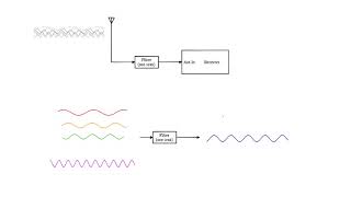
RF filters play a crucial role in signal processing by allowing specific frequency ranges to pass while attenuating others. The main considerations in the design of RF filters include:
- Cutoff Frequency: This is the frequency at which the filter begins attenuating signals. It's essential to accurately determine the cutoff frequency to ensure the filter only allows the desired frequencies to pass.
- Quality Factor (Q): The Q factor indicates the selectivity of the filter. A higher Q results in a narrower bandwidth, leading to sharper filtering, but it may also introduce more losses at the cutoff frequency.
- Impedance Matching: Effective impedance matching between the filter and the overall system is necessary to maximize power transfer and reduce reflections, which can degrade the signal quality.
- Filter Order: The order of the filter affects how steeply the filter attenuates frequencies outside its passband. Higher-order filters provide better selectivity but may be more complex to design and necessitate additional components.
Incorporating these considerations is essential for optimizing RF filter performance in communication systems and various applications.
Youtube Videos
Audio Book
Dive deep into the subject with an immersive audiobook experience.
Cutoff Frequency
Chapter 1 of 4
🔒 Unlock Audio Chapter
Sign up and enroll to access the full audio experience
Chapter Content
● Cutoff Frequency: The cutoff frequency of a filter determines the point where the filter begins to attenuate the signal. The filter should be designed to pass signals within the desired frequency range and reject unwanted frequencies.
Detailed Explanation
The cutoff frequency is a critical design parameter in filter design. It defines the boundary between the frequencies that the filter allows to pass and those it attenuates. For example, in a low-pass filter, frequencies below the cutoff can pass through, while those above are gradually reduced in amplitude. To effectively design a filter, it's essential to determine what frequency range you want to allow and what you want to block, which involves calculating the correct cutoff frequency based on the application's requirements.
Examples & Analogies
Think of the cutoff frequency as a gate in a fence around a garden. The gate only opens wide enough to let in certain plants (frequencies) while keeping out weeds (unwanted frequencies). If you set the gate properly, you'll have a thriving garden inside while blocking out everything that could harm it.
Quality Factor (Q)
Chapter 2 of 4
🔒 Unlock Audio Chapter
Sign up and enroll to access the full audio experience
Chapter Content
● Quality Factor (Q): The Q factor defines the selectivity of the filter. A higher Q factor results in a narrower bandwidth, providing sharper filtering. However, high-Q filters may introduce more loss at the cutoff frequency.
Detailed Explanation
The Quality Factor, or Q, is a measure of how selective a filter is at its cutoff frequency. A high Q means the filter will only allow a very narrow band of frequencies to pass, making it effective at isolating specific signals. However, achieving a high Q often comes at a cost; it can lead to increased insertion loss at the cutoff frequency, which means that even the desired signal might be attenuated more than expected. Thus, there's a balance to be struck between selectivity (Q) and signal integrity (loss).
Examples & Analogies
Imagine tuning a radio to a specific station. A high Q filter is like having a very precise tuning dial; it allows you to focus only on your favorite channel while minimizing noise from others. However, if your tuner is too precise, it might make it hard to keep a stable connection with that station if the signal fluctuates slightly.
Impedance Matching
Chapter 3 of 4
🔒 Unlock Audio Chapter
Sign up and enroll to access the full audio experience
Chapter Content
● Impedance Matching: Filters need to be impedance-matched to the rest of the system to ensure efficient power transfer and minimize reflection. Impedance matching networks are often used in conjunction with filters.
Detailed Explanation
Impedance matching is crucial in ensuring that the filter integrates well with other components in a circuit. When impedances are mismatched, signals can reflect back, causing loss and distortion. To maximize the power transferred through the filter, the input and output impedances should match the characteristic impedance of the system (commonly 50 or 75 ohms in RF applications). This might involve adding matching networks, which can include inductors and capacitors that help adjust the impedance seen by the filter.
Examples & Analogies
Think of impedance matching like connecting a garden hose to a spray nozzle. If the hose fits nicely with the nozzle (matched impedance), water flows smoothly without leaks. But if the hose is too wide or too narrow for the nozzle, water will spill out (reflections) and you won't get efficient spray coverage.
Filter Order
Chapter 4 of 4
🔒 Unlock Audio Chapter
Sign up and enroll to access the full audio experience
Chapter Content
● Filter Order: The order of the filter determines the steepness of the roll-off and the sharpness of the cutoff. Higher-order filters provide better selectivity but may require more components.
Detailed Explanation
The order of a filter is fundamentally about its complexity and performance characteristics. A filter's order is determined by the number of reactive components (capacitors and inductors) in the circuit. Higher-order filters can achieve a steeper roll-off at the cutoff frequency, meaning they can more sharply distinguish between allowed and blocked frequencies. However, with increased order comes a more complex design that may be more challenging to build and require more components, making it potentially expensive and bulky.
Examples & Analogies
Consider the filters used in a quality coffee maker. A single-layer mesh might filter out large coffee grounds but let fine particles pass through, while a multi-layer filtering system can catch even the tiniest particles, leading to a much smoother cup of coffee. Similarly, higher-order filters provide a finer degree of frequency selection.
Key Concepts
-
Cutoff Frequency: The point where the signal is attenuated.
-
Quality Factor (Q): Selectivity measure, affecting filter performance.
-
Impedance Matching: Ensures efficiency by maximizing power transfer.
-
Filter Order: Determines steepness of the frequency response.
Examples & Applications
A low-pass filter design that appropriately sets a cutoff frequency of 1 kHz to remove high-frequency noise from audio signals.
A high-pass filter configured with a cutoff frequency of 100 Hz used in a system to eliminate unwanted low-frequency noise from a signal.
Memory Aids
Interactive tools to help you remember key concepts
Rhymes
To keep your signals clear and bright, match your impedance just right.
Stories
Imagine a gatekeeper carefully deciding which audio signals enter the concert hall and which ones are turned away. This is like the cutoff frequency managing what passes through a filter.
Memory Tools
C-A-P for Cutoff, Application, and Passband helps remember what factors to consider in filter design.
Acronyms
S-L-O-W for Selectivity, Losses, Optimization, Wavelength reminds you to balance performance aspects while designing.
Flash Cards
Glossary
- Cutoff Frequency
The frequency at which a filter starts to significantly attenuate the signal.
- Quality Factor (Q)
A measure of the selectivity of the filter, defined as the ratio of the center frequency to the bandwidth.
- Impedance Matching
The practice of making the impedance of a load match the source impedance to maximize power transfer.
- Filter Order
A numerical measure of the filter's complexity and its ability to steeply roll off unwanted frequencies.
Reference links
Supplementary resources to enhance your learning experience.