
Summary of Key Concepts
Interactive Audio Lesson
Listen to a student-teacher conversation explaining the topic in a relatable way.
RF Amplifiers Overview
🔒 Unlock Audio Lesson
Sign up and enroll to listen to this audio lesson

Today, we’re discussing RF amplifiers, which play a key role in amplifying weak RF signals. Can anyone tell me why it's important to minimize noise and distortion?

Because it affects the quality of the received signal!

Yes! If there's too much noise, we can't hear the original signal clearly.
Exactly! RF amplifiers also come in different configurations. Does anyone remember them?

Common-emitter, common-collector, and common-base amplifiers!
Correct! Can someone explain the main purpose of the common-collector amplifier?

It’s used for impedance matching, right?
Yes! Great job, everyone! Remember, choosing the right amplifier configuration is crucial for optimal performance.
RF Filters Explained
🔒 Unlock Audio Lesson
Sign up and enroll to listen to this audio lesson

Let’s switch gears and talk about RF filters. Who can tell me what an RF filter does?
It selects or rejects certain frequencies!
Yeah! Like a low-pass filter that allows low frequencies through!
Exactly! There are different types of filters, including low-pass, high-pass, band-pass, and band-stop. Any thoughts on when we might use a band-stop filter?
For eliminating interference at a specific frequency?
Right again! Filters help us clean our signal from unwanted noise. Now, what must we consider when designing these filters?
The cutoff frequency and quality factor!
Spot on! The trade-offs in Q factor can significantly affect our design. Let's ensure we can all design filters effectively.
Design Considerations in RF Components
🔒 Unlock Audio Lesson
Sign up and enroll to listen to this audio lesson
As we move towards designing RF amplifiers and filters, why is stability so essential?
To avoid oscillations or unwanted signals?
Exactly! And what about noise figure? How does it impact our designs?
A lower noise figure means the amplifier adds less noise to the signal!
Yes! Maintaining a low noise figure is key for preserving signal quality. And what about impedance matching?
It helps prevent signal loss and reflections between different components!
Great summary, everyone! Remember these considerations—they're vital for effective RF designs!
Introduction & Overview
Read summaries of the section's main ideas at different levels of detail.
Quick Overview
Standard
RF amplifiers are crucial for amplifying weak RF signals while minimizing noise and distortion, incorporating configurations like common-emitter, common-collector, and common-base. RF filters serve to select or reject specific frequencies, with essential types including low-pass, high-pass, band-pass, and band-stop filters.
Detailed
Summary of Key Concepts
RF Amplifiers
RF amplifiers are designed to increase the amplitude of weak RF signals while minimizing noise, distortion, and unwanted reflections. The key configurations include:
- Common-Emitter Amplifier: Provides high voltage gain with moderate impedance.
- Common-Collector Amplifier: Offers unity voltage gain, high current gain, and is primarily used for impedance matching.
- Common-Base Amplifier: Features high voltage gain with low input impedance, suitable for high-frequency applications.
Design considerations for RF amplifiers include:
- Gain: Ensuring sufficient amplification and signal integrity.
- Bandwidth: Operating within the desired frequency range.
- Noise Figure (NF): Maintaining signal quality with a low noise figure.
- Impedance Matching: Preventing signal loss and reflections.
- Linearity & Stability: Providing linear amplification across a wide frequency range.
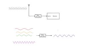
RF Filters
RF filters are integral to RF systems for selecting or rejecting specific frequencies. Common types include:
- Low-Pass Filter (LPF): Passes frequencies below a certain threshold while attenuating higher frequencies.
- High-Pass Filter (HPF): Passes frequencies above a specific threshold, used in signal conditioning.
- Band-Pass Filter (BPF): Allows a specific range of frequencies to pass, ideal for communication systems.
- Band-Stop Filter (BSF): Attenuates a particular frequency range to eliminate interference.
Key design considerations for RF filters include:
- Cutoff Frequency: Determines the point of signal attenuation.
- Quality Factor (Q): Higher Q indicates sharper filtering.
- Impedance Matching: Essential to ensure efficient power transfer.
- Filter Order: Higher orders yield better selectivity but require more components.
Youtube Videos
Audio Book
Dive deep into the subject with an immersive audiobook experience.
Overview of RF Amplifiers
Chapter 1 of 3
🔒 Unlock Audio Chapter
Sign up and enroll to access the full audio experience
Chapter Content
● RF Amplifiers: Used to amplify weak RF signals while minimizing noise, distortion, and unwanted reflections. The basic configurations include common-emitter, common-collector, and common-base amplifiers.
Detailed Explanation
RF amplifiers are essential components in RF circuits, designed specifically to boost weak radio frequency signals. They help enhance the strength of these signals with the aim of ensuring that they can be processed effectively in various applications. Importantly, these amplifiers must also reduce accompanying noise and distortion to maintain signal integrity and prevent unwanted reflections that can interfere with the desired signal. The three primary configurations—common-emitter, common-collector, and common-base—each offer distinct characteristics and advantages, making them suitable for different applications. For instance, the common-emitter configuration is popular for voltage gain, while the common-collector is preferred for buffering signals due to its high input and low output impedance.
Examples & Analogies
Think of an RF amplifier as a megaphone for a person trying to communicate in a crowded area. Just as the megaphone amplifies the speaker's voice while filtering out surrounding noise, RF amplifiers boost weak radio signals, making them clearer and stronger, allowing for effective communication even in noisy environments.
Overview of RF Filters
Chapter 2 of 3
🔒 Unlock Audio Chapter
Sign up and enroll to access the full audio experience
Chapter Content
● RF Filters: Used to select or reject specific frequencies. Common filter types include low-pass, high-pass, band-pass, and band-stop filters. Design considerations include cutoff frequency, quality factor, and impedance matching.
Detailed Explanation
RF filters play a crucial role in managing the frequencies that pass through or are blocked from a signal. They allow certain frequency ranges to pass while attenuating or removing others to ensure signal clarity in communication systems. The key types of filters include low-pass filters, which permit frequencies below a set threshold; high-pass filters, which allow frequencies above a threshold; band-pass filters, which allow a specific range of frequencies; and band-stop filters, which block a specific frequency range. Designing these filters involves critical considerations such as the cutoff frequency, which defines where filtering begins, and the quality factor (Q), which indicates how selective the filter is. Additionally, impedance matching ensures that the filters work efficiently with the other components they interface with.
Examples & Analogies
You can think of RF filters like a bouncer at a nightclub. The bouncer (the filter) decides who gets in (the frequencies that are allowed to pass) and who has to stay out (the frequencies that are filtered out). Just as the bouncer needs to maintain the right atmosphere within the club (clear signal quality), RF filters are designed to optimize the desired signals while blocking out the unwanted 'noise' that might disrupt effective communication.
Importance of Design and Analysis
Chapter 3 of 3
🔒 Unlock Audio Chapter
Sign up and enroll to access the full audio experience
Chapter Content
● Design and Analysis: Designing RF amplifiers and filters requires a solid understanding of component behavior at high frequencies, as well as practical techniques for impedance matching, gain control, and filtering.
Detailed Explanation
The design and analysis of RF amplifiers and filters are vital for creating functional and efficient RF systems. A deep understanding of how various components behave at high frequencies is essential, as performance can vary significantly compared to low-frequency designs. Techniques like impedance matching are critical to ensure that signals transfer effectively without reflections, which can degrade performance. Additionally, gain control is vital to ensure that the amplifiers provide the necessary boost without introducing distortion. Lastly, selecting and implementing the right filtering techniques helps in achieving the desired signal clarity across the frequency spectrum.
Examples & Analogies
Imagine you are preparing a recipe that requires the precise combination of ingredients. Each ingredient represents a different component in an RF circuit. Just as you need to understand the properties of the ingredients—what happens when you mix them together, how cooking times affect the outcome—you must analyze and design RF circuits with an understanding of how each component interacts at high frequencies for optimal performance.
Key Concepts
-
RF Amplifiers: Devices that amplify weak RF signals.
-
Filter Types: Low-pass, high-pass, band-pass, and band-stop filters used for frequency selection.
-
Design Considerations: Key factors in amplifier and filter design include gain, bandwidth, noise figure, impedance matching, and stability.
Examples & Applications
A common-emitter amplifier used in a radio transmitter to amplify weak incoming signals before they are processed.
A band-pass filter in a communication system that isolates the desired frequency range for better signal clarity.
Memory Aids
Interactive tools to help you remember key concepts
Rhymes
Amplifiers amplify, keep noise low,
Stories
Imagine an RF signal as a whisper in a crowded café. The amplifier is your friend who raises their voice just enough to be heard, while the filters act like your focus, tuning into only what you want to hear.
Memory Tools
For remembering RF filter types: "L-H-B-S (Low, High, Band-Pass, Band-Stop) are the filters on my stop!"
Acronyms
Remember 'GHNIS' for key design considerations
Gain
Noise figure
Impedance matching
Stability.
Flash Cards
Glossary
- RF Amplifier
A device that amplifies weak radio frequency signals while minimizing noise and distortion.
- CommonEmitter Amplifier
A basic amplifier configuration providing high voltage gain.
- CommonCollector Amplifier
An amplifier configuration used for impedance matching, offering a low output impedance.
- CommonBase Amplifier
An amplifier configuration with high voltage gain and low input impedance, suitable for high-frequency applications.
- LowPass Filter
A filter that allows frequencies below a certain cutoff frequency to pass while attenuating higher frequencies.
- HighPass Filter
A filter that allows frequencies above a certain cutoff frequency to pass while attenuating lower frequencies.
- BandPass Filter
A filter that allows a specific range of frequencies to pass through while rejecting others.
- BandStop Filter
A filter that attenuates a specific range of frequencies while allowing frequencies outside this range to pass.
Reference links
Supplementary resources to enhance your learning experience.