
RF Amplifiers
Interactive Audio Lesson
Listen to a student-teacher conversation explaining the topic in a relatable way.
Common-Emitter Amplifier
🔒 Unlock Audio Lesson
Sign up and enroll to listen to this audio lesson

Today, we will discuss the common-emitter amplifier, a fundamental configuration in RF circuits. Can anyone tell me what they think the primary function of an RF amplifier is?

To amplify RF signals?
Exactly! The common-emitter amplifier provides high voltage gain. It has moderate input and output impedance and is often used in low-power RF applications. Can anyone recall the gain equation for this type of amplifier?

Is it Av = -RC/re?
Great job! That's the correct equation. Remember, RC is the collector resistance, and re is the internal emitter resistance. Now, why is a high voltage gain important in communication systems?

It helps in boosting weak signals for clearer transmission!
Exactly! Amplifying weak signals while minimizing distortion is crucial. Let's summarize: the common-emitter amplifier is central to RF applications due to its high voltage gain and moderate impedance characteristics.
Common-Collector Amplifier
🔒 Unlock Audio Lesson
Sign up and enroll to listen to this audio lesson

Next, let’s discuss the common-collector amplifier, also known as the emitter follower. What do you think makes this configuration unique?

Is it that it has low voltage gain?
Correct! It typically has a unity gain. However, it is excellent for impedance matching. Who remembers the gain equation for this configuration?
It's Av = 1 - RL/(RE + re)!
Yes! High input impedance and low output impedance make it effective for buffering signals. Why do we need buffering in RF circuits?
To avoid loading down the previous stage and ensure signal integrity.
Exactly! Let's summarize that the common-collector amplifier is crucial for impedance matching, offering a low output impedance that benefits circuit design.
Common-Base Amplifier
🔒 Unlock Audio Lesson
Sign up and enroll to listen to this audio lesson
Now, let’s explore the common-base amplifier. This one is a bit different. Can anyone tell me what stands out in its characteristics?
It has high voltage gain but low input impedance, right?
Absolutely! It's mainly used in high-frequency applications where impedance matching is critical. The gain equation is similar to the common-emitter. Who can tell me why low input impedance might be a disadvantage?
It could affect how the amplifier interacts with previous circuit stages?
Right! It might not interface well with high-impedance sources. To summarize, the common-base amplifier is ideal for high-frequency applications despite its low input impedance.
Design Considerations
🔒 Unlock Audio Lesson
Sign up and enroll to listen to this audio lesson
Now that we understand the configurations, let’s talk about design considerations for RF amplifiers. What do you think is the most critical factor?
Gain, to properly amplify signals?
Exactly! High gain is essential. Other considerations include bandwidth, noise figure, and impedance matching. Can anyone explain why a low noise figure (NF) is important?
Because it affects the quality of the amplified signal!
Correct! A low NF maintains signal clarity. What about stability? Why is that necessary in RF design?
To prevent unwanted oscillations and ensure reliable operation!
Precisely! Stability across frequency is crucial in RF amplifiers. Let’s recap: key design considerations include gain, bandwidth, noise figure, impedance matching, linearity, and stability.
Lab Work
🔒 Unlock Audio Lesson
Sign up and enroll to listen to this audio lesson
Finally, we will discuss our lab work on RF amplifiers. What do you think will be our main goal?
To design and analyze an RF amplifier?
Yes! Designing an RF amplifier to amplify a weak signal is our objective. What materials do you think we will need for this lab?
Transistors, resistors, capacitors, and an oscilloscope?
Exactly! After building the circuit, we will measure the output to calculate gain and ensure linearity and stability. Why is hands-on experience valuable in understanding RF amplifiers?
It helps us apply theoretical knowledge to real-world scenarios!
Correct! Practical work reinforces our understanding of amplifiers and their applications. Let's summarize our lab objectives and what we hope to accomplish.
Introduction & Overview
Read summaries of the section's main ideas at different levels of detail.
Quick Overview
Standard
This section dives into RF amplifiers, detailing their configurations, design considerations, and practical lab applications. Key configurations include common-emitter, common-collector, and common-base amplifiers. Essential design factors, such as gain, bandwidth, noise figure, impedance matching, linearity, and stability, are also discussed.
Detailed
RF Amplifiers
RF amplifiers are crucial components in RF and HF circuits, used to amplify weak signals and ensure effective communication. This section is divided into three main subtopics:
1. Basic Configurations of RF Amplifiers
- Common-Emitter (CE) Amplifier: Known for high voltage gain, moderate input and output impedance, and following the gain equation: \(A_v = -\frac{R_C}{r_e}\).
- Common-Collector (CC) Amplifier: Also known as the emitter follower, it provides unity gain, high input impedance, and is used for impedance matching. The gain equation is: \(A_v = 1 - \frac{R_L}{R_E + r_e}\).
- Common-Base (CB) Amplifier: Primarily used in high-frequency applications with low input impedance but high voltage gain, sharing the same gain equation as the common-emitter amplifier.
2. RF Amplifier Design Considerations
When designing RF amplifiers, several critical factors must be considered:
- Gain: Essential for amplifying weak signals effectively while preserving integrity.
- Bandwidth: The amplifier should operate over the required frequency range while maintaining performance.
- Noise Figure (NF): Keeping the noise figure low is vital for quality signal amplification.
- Impedance Matching: Essential to prevent signal loss and optimize power transfer.
- Linearity and Stability: Avoiding distortion and ensuring stable operation across frequencies.
3. Lab Work on RF Amplifiers
Hands-on experience is key in understanding RF amplifiers. The lab objective involves designing and analyzing an RF amplifier to amplify weak signals, utilizing various components like transistors, resistors, capacitors, and oscilloscopes. Students learn to design circuits based on frequency and gain requirements while measuring output signals for validation.
Through studying RF amplifiers' configurations and design considerations, students gain vital insights into their applications in communication, broadcasting, and radar systems. Understanding the operational characteristics of amplifiers is foundational for further studies in electronics and communications.
Youtube Videos
Audio Book
Dive deep into the subject with an immersive audiobook experience.
Introduction to RF Amplifiers
Chapter 1 of 6
🔒 Unlock Audio Chapter
Sign up and enroll to access the full audio experience
Chapter Content
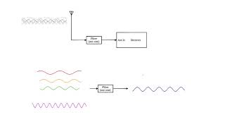
RF amplifiers are designed to amplify signals at high frequencies, typically from a few kHz to several GHz. The primary challenge in RF amplifier design is to maintain high gain while minimizing distortion, noise, and unwanted signal reflections.
Detailed Explanation
RF amplifiers are essential components in various electronic systems used to boost weak radio frequency signals. They operate within a range of frequencies from a few kilohertz (kHz) to several gigahertz (GHz). However, creating effective RF amplifiers poses challenges in maintaining a high signal gain. This means that they should successfully increase signal strength without introducing significant distortion (unwanted changes to the signal), extra noise (unwanted electrical signals), or signal reflections (where the signal bounces back instead of continuing on its path).
Examples & Analogies
You can think of an RF amplifier like a megaphone at a concert. Just as a megaphone amplifies a person's voice so that everyone in a large crowd can hear it without adding extra noise or distortion, RF amplifiers boost weak signals in communication systems to ensure clarity over long distances.
Basic Configurations of RF Amplifiers
Chapter 2 of 6
🔒 Unlock Audio Chapter
Sign up and enroll to access the full audio experience
Chapter Content
Common-Emitter (CE) Amplifier:
The common-emitter amplifier is a basic configuration used in both low- and high-frequency applications. It provides voltage gain and is widely used in low-power RF circuits.
Characteristics:
- High voltage gain.
- Moderate input and output impedance.
- Gain Equation:
- Av=−RCreA_v = -\frac{R_C}{r_e}
Where RCR_C is the collector resistance, and rer_e is the internal emitter resistance.
Detailed Explanation
The Common-Emitter or CE amplifier is a fundamental design frequently used in RF applications. It is capable of amplifying voltage significantly, making it useful for enhancing weak signals in various circuits. This design is characterized by its high voltage gain and moderate input and output impedance levels. The gain equation, which describes the amplifier's performance, indicates that the voltage gain (Av) depends on the ratio of collector resistance (RC) to emitter resistance (re), showcasing how variations in these resistances can influence the output signal's strength.
Examples & Analogies
Imagine a speaker that can amplify sound. The CE amplifier works like a speaker that increases sound volume based on the input sound level (i.e., weak voice). The collector resistance is akin to how loud the speaker can get, while the emitter resistance is like how much effort it takes for the speaker to operate. If adjusted correctly, the speaker can pump out sound that fills a large space — just as the CE amplifier can strengthen weak RF signals significantly.
Common-Collector (CC) Amplifier
Chapter 3 of 6
🔒 Unlock Audio Chapter
Sign up and enroll to access the full audio experience
Chapter Content
Common-Collector (CC) Amplifier:
This configuration is known as the emitter follower and is used for impedance matching and providing a low output impedance. The gain is typically less than 1, but it is used to buffer signals.
Characteristics:
- Low voltage gain (unity gain).
- High current gain.
- High input impedance and low output impedance.
- Gain Equation:
- Av=1−RLRE+reA_v = 1 - \frac{R_{L}}{R_E + r_e}
Where RLR_L is the load resistance, and RER_E is the emitter resistance.
Detailed Explanation
The Common-Collector or CC amplifier, often referred to as an emitter follower, is primarily utilized for impedance matching. It effectively maintains a balance between input and output impedances, facilitating the transfer of signals between different circuit stages. Although the voltage gain is typically around 1 (unity), this configuration provides excellent current gain, making it ideal for buffering signals without significantly altering their amplitude. The gain equation shows that the amplifier's gain is influenced by both the load and emitter resistances, allowing designers to fine-tune its performance.
Examples & Analogies
Think of the CC amplifier like a bridge between two highways. The bridge allows cars (signals) to flow smoothly from a wide highway (high input impedance) to a narrower street (low output impedance) without causing any jams or congestion. Even if the speed doesn’t increase much (unity gain), it ensures that traffic can continue without interruption, similar to how the CC amplifier conditions signals so they can be effectively processed downstream.
Common-Base (CB) Amplifier
Chapter 4 of 6
🔒 Unlock Audio Chapter
Sign up and enroll to access the full audio experience
Chapter Content
Common-Base (CB) Amplifier:
The common-base amplifier has a high voltage gain but very low input impedance. It is used primarily in high-frequency applications where impedance matching is required, especially for low-noise amplification.
Characteristics:
- High voltage gain.
- Low input impedance.
- Gain Equation:
- Av=−RCreA_v = -\frac{R_C}{r_e}
Similar to the common-emitter amplifier.
Detailed Explanation
The Common-Base or CB amplifier is a specialized configuration that features high voltage gain along with very low input impedance. This makes it particularly useful in applications operating at high frequencies, where signal integrity is paramount. The gain equation mirrors that of the CE amplifier, indicating that it also boosts signals while maintaining efficiency. The low input impedance, however, means that care must be taken when integrating the CB amplifier into a circuit to ensure compatibility with other components.
Examples & Analogies
Imagine a high-performance sports car (the CB amplifier) that can achieve incredible speeds (high voltage gain), but has a very narrow garage entrance (low input impedance). It zooms past traffic (providing high gain), but drivers must be cautious about how they approach the garage. In the world of amplifiers, while it can accelerate signals quickly, connecting it to the wrong circuit can lead to problems, similar to a car getting stuck in a garage too small for it.
RF Amplifier Design Considerations
Chapter 5 of 6
🔒 Unlock Audio Chapter
Sign up and enroll to access the full audio experience
Chapter Content
RF Amplifier Design Considerations:
- Gain: High gain is a primary objective in RF amplifier design. The amplifier should provide sufficient amplification to weak input signals while maintaining signal integrity.
- Bandwidth: The amplifier should be designed to operate over the required frequency range. The bandwidth of the amplifier is a critical parameter, particularly in communication systems.
- Noise Figure (NF): In RF circuits, the noise figure measures how much noise the amplifier adds to the signal. A low noise figure is crucial for maintaining signal quality.
- Impedance Matching: Ensuring proper impedance matching between the amplifier’s input, output, and the rest of the system is essential to prevent signal loss and reflections.
- Linearity: The amplifier should provide linear amplification to avoid distortion of the amplified signal.
- Stability: RF amplifiers must be stable across a wide frequency range, avoiding oscillations and maintaining reliable performance.
Detailed Explanation
When designing RF amplifiers, several key considerations must be kept in mind to ensure efficient operation. First and foremost is gain, where the goal is to provide strong amplification of weak input signals without sacrificing clarity. Bandwidth refers to the range of frequencies the amplifier can effectively handle, making it a crucial factor for applications in communication. The noise figure (NF) measures the additional noise introduced by the amplifier, and minimizing this ensures high-quality signals. Proper impedance matching is vital to prevent energy loss between the amplifier and other components. Additionally, amplifiers should maintain linearity to produce accurate and undistorted output signals. Finally, stability across a wide frequency range is important to prevent the risk of oscillations that could disrupt performance.
Examples & Analogies
Consider the design of a concert sound system. You need to amplify sound (gain) so that everyone can hear, but you must also ensure it covers the entire area (bandwidth). If the speakers add too much noise (noise figure), people won't enjoy the music. Similar to adjusting speaker placement to avoid feedback (impedance matching), you want to ensure everything works together seamlessly. Just as a sound engineer ensures the mix sounds good at different volumes (linearity) without causing feedback (stability), RF amplifier designers do the same to maintain signal quality.
Lab Work on RF Amplifiers
Chapter 6 of 6
🔒 Unlock Audio Chapter
Sign up and enroll to access the full audio experience
Chapter Content
Lab Work on RF Amplifiers:
- Objective: Design and analyze an RF amplifier to amplify a weak RF signal.
- Materials:
- Transistor or FET (e.g., BJT for common-emitter, FET for common-source)
- Resistors, capacitors for biasing and stabilization
- Signal generator and oscilloscope
- Power supply
- Procedure:
- Design the amplifier circuit based on the desired frequency range and gain.
- Build the amplifier and apply a weak RF signal.
- Measure the output signal to calculate the gain and check for linearity and stability.
Detailed Explanation
The lab work involving RF amplifiers revolves around practical experience in designing and analyzing circuits that can boost weak signals. The objective is to create an RF amplifier that enhances a weak RF signal effectively. The materials needed include crucial electronic components like transistors or FETs, resistors, capacitors, and essential instruments like a signal generator and oscilloscope. The procedure starts with designing the amplifier circuit, focusing on its intended frequency range and gain requirements. After building the circuit, a weak RF signal is supplied for amplification. Finally, measuring the output signal allows for calculating the gain and assessing the amplifier's linearity and stability, which are key performance indicators.
Examples & Analogies
Building an RF amplifier can be likened to cooking a new recipe. Just like you gather ingredients (components), measure everything according to the recipe (circuit design), and prepare each step (building the circuit), the process of creating an RF amplifier involves careful planning and execution. After cooking, you taste the dish (measure the output) to see if it meets your expectations (gain, linearity, stability). If it tastes good, you know you’ve followed the recipe well!
Key Concepts
-
Common-Emitter Amplifier: A configuration providing high voltage gain, widely used in RF applications.
-
Common-Collector Amplifier: Also known as the emitter follower, emphasizes unity gain and impedance matching.
-
Common-Base Amplifier: Designed for high-frequency applications with high gain but low input impedance.
-
Gain: A critical measurement in amplifiers indicating how much an amplifier increases signal amplitude.
-
Bandwidth: The range within which the amplifier can operate effectively.
-
Noise Figure: Indicates how much noise an amplifier introduces relative to the input signal.
-
Impedance Matching: Important for maximizing power transfer and minimizing signal loss.
-
Linearity: Desirable trait for consistent amplification without distortion.
-
Stability: Ensures reliable performance of amplifiers across frequency variations.
Examples & Applications
In a communications system, a common-emitter amplifier is employed to boost the weak signals captured by antennas.
A common-collector amplifier is perfect for buffering audio signals from a high impedance source before sending them to a speaker.
Memory Aids
Interactive tools to help you remember key concepts
Rhymes
In circuits where weak signals play, amplifiers boost them on their way.
Stories
A radio engineer had a small antenna, capturing the faintest signals. With a common-emitter amplifier, he watched as whispers turned into clear tunes, transforming distant music into vibrant sound.
Memory Tools
For RF amplifiers remember: G-BNIS (Gain, Bandwidth, Noise figure, Impedance matching, Stability) - these are crucial considerations.
Acronyms
CE for 'Common Emitter' amplifies well; CC for 'Collector' indicates a buffering shell.
Flash Cards
Glossary
- CommonEmitter Amplifier
An amplifier configuration that provides high voltage gain and is widely used in various RF applications.
- CommonCollector Amplifier (Emitter Follower)
An amplifier configuration known for unity voltage gain and high input impedance used for impedance matching.
- CommonBase Amplifier
An amplifier configuration used primarily in high-frequency applications with a high voltage gain but low input impedance.
- Gain
The ratio of output signal power to input signal power in an amplifier.
- Bandwidth
The range of frequencies over which an amplifier operates effectively.
- Noise Figure (NF)
A measure of an amplifier's contribution to the total noise of the system.
- Impedance Matching
The technique used to ensure maximum power transfer between components in a circuit.
- Linearity
The ability of an amplifier to produce an output that is a linear function of the input.
- Stability
The property of an amplifier to avoid oscillations and maintain consistent performance across a range of frequencies.
Reference links
Supplementary resources to enhance your learning experience.