
Forward Kinematics
Enroll to start learning
You’ve not yet enrolled in this course. Please enroll for free to listen to audio lessons, classroom podcasts and take practice test.
Interactive Audio Lesson
Listen to a student-teacher conversation explaining the topic in a relatable way.
Introduction to Forward Kinematics
🔒 Unlock Audio Lesson
Sign up and enroll to listen to this audio lesson

Today, we are diving into Forward Kinematics, which is crucial for determining where a robot's end-effector will be based on its joint movements. Does anyone know why this concept is important in robotics?

I think it's important because we need to know where the robot's tool will be to perform tasks accurately.
Exactly! Knowing the end-effector's position allows robots to perform precise operations like 3D printing or automated welding. Now, could anyone summarize our goal when we apply Forward Kinematics?

We need to find the end-effector's position and orientation based on the joint parameters.
Perfect! That's our foundational goal.
Denavit-Hartenberg Parameters
🔒 Unlock Audio Lesson
Sign up and enroll to listen to this audio lesson

Let's now talk about the Denavit-Hartenberg parameters. They are a standardized way of defining the geometry of the robot. What are the four D-H parameters?

Theta, d, a, and alpha!
That's right! Each parameter plays a key role in determining how joint movements relate to the position and orientation of the end-effector. Can anyone explain what theta represents?

Theta represents the joint angle!
Good memory! Remembering these names can help us as we proceed. One way to memorize them is using the acronym 'TDAL' - Theta, d, a, and Alpha.
Transformation Matrix
🔒 Unlock Audio Lesson
Sign up and enroll to listen to this audio lesson
Now, let's focus on the transformation matrix. Who can tell me why we use a 4x4 matrix in Forward Kinematics?
Is it because it includes both rotation and translation?
Exactly! This matrix combines our transformations efficiently. It allows a cohesive transition from one coordinate frame to another. Can someone break down the components of this matrix?
It includes cosine and sine terms that relate to the rotation and translation of the joint.
Good job! Now, when we combine these matrices, what equation reflects the overall transformation?
Tn = T0 ⋅ T1 ⋅ T2 … Tn−1!
Very well! This equation helps us find the end-effector's final position.
Chain Multiplication
🔒 Unlock Audio Lesson
Sign up and enroll to listen to this audio lesson
Now that we know how to create transformation matrices, how do we use them together? What do we call this process of combining them?
Chain multiplication!
Exactly! When we chain multiple matrices together, we can find the overall transformation that gives the end-effector's position and orientation. Can anyone summarize why this is critical in robotics?
Because it allows us to compute the exact location and orientation of the end-effector, which is vital for automation tasks.
Well put! This understanding is essential as it forms the basis for further advanced kinematics, like inverse kinematics.
Applications and Significance
🔒 Unlock Audio Lesson
Sign up and enroll to listen to this audio lesson
Let's wrap up by discussing where we see Forward Kinematics applied in the real world. What are some applications?
Robotic arms for tasks like assembly, welding, or even 3D printing!
Correct! Each task requires precise control of the robot's end-effector position. How is FK beneficial in these scenarios?
It ensures that the robot can accurately reach and interact with the objects in its environment.
Exactly! Forward Kinematics is vital for efficient and effective operation in many robotic applications.
Introduction & Overview
Read summaries of the section's main ideas at different levels of detail.
Quick Overview
Standard
Forward Kinematics utilizes Denavit-Hartenberg (D-H) parameters to derive the transformation matrices for robotic joints, allowing for the precise determination of a robot's end-effector position and orientation given specific joint parameters. It is essential for the successful operation of manipulative robots in various applications.
Detailed
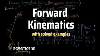
Forward Kinematics
Forward Kinematics (FK) is a fundamental concept in robotics that involves computing the position and orientation of a robot's end-effector based on its joint parameters. This section explores the essential aspects of FK, highlighting the Denavit-Hartenberg (D-H) parameters, transformation matrices, and chain multiplication, crucial for understanding how robots achieve accurate positioning.
Denavit-Hartenberg Parameters
The D-H convention simplifies the representation of robotic arms by standardizing the coordinate frame assignment to each link in the manipulator. The four D-H parameters are:
1. θ (Theta): The joint angle which specifies the rotation about the joint axis.
2. d: The link offset, representing the distance along the previous joint's axis to the common normal.
3. a: The link length, representing the distance between the previous joint's z-axis to the current joint's z-axis.
4. α (Alpha): The link twist, defining the angle around the common normal from the previous joint's z-axis to the current joint's z-axis.
These parameters are crucial in forming the transformation matrix for each joint.
Transformation Matrix
Each joint's transformation can be represented by a 4x4 homogeneous transformation matrix
($T_i^{i-1}$).
This matrix encapsulates both the rotation and translation needed to transform the position of a link relative to another. The overall transformation of the link from the base to the end-effector can then be derived by multiplying these individual matrices:
$$T_n = T_0 ⋅ T_1 ⋅ T_2 ⋯ T_{n−1}$$
This equation leads to the determination of the end-effector's position (x, y, z) and orientation.
Significance
Understanding FK is essential for applications such as robotic arms used in construction, 3D printing, automated welding, and many other areas in civil engineering where precise manipulation of objects is required. FK allows robots to operate efficiently in these tasks by providing a clear calculation method for the desired end-effector positioning.
Youtube Videos

Audio Book
Dive deep into the subject with an immersive audiobook experience.
Overview of Forward Kinematics
Chapter 1 of 4
🔒 Unlock Audio Chapter
Sign up and enroll to access the full audio experience
Chapter Content
Forward Kinematics (FK) involves calculating the position and orientation of the robot’s end-effector using the known joint parameters.
Detailed Explanation
Forward Kinematics (FK) is the process used in robotics to determine where the robot's end-effector (for example, a hand or tool) will be in space, based on predefined movements of its joints. When we know the angles or positions of the joints (the parameters), FK allows us to compute the corresponding position and orientation of the end-effector. In simpler terms, if you know how a robot is articulated (its joint positions), FK helps us find out where the robot's 'hand' is going to be located.
Examples & Analogies
Imagine you have a toy robot arm with joints that you can move. If you rotate the elbow and shoulder joints to certain angles, you can picture where the hand of the robot would end up. Forward kinematics is like saying, 'If I move this joint this way, where will my hand be?'.
Denavit-Hartenberg (D-H) Parameters
Chapter 2 of 4
🔒 Unlock Audio Chapter
Sign up and enroll to access the full audio experience
Chapter Content
The D-H convention standardizes the assignment of coordinate frames to robotic links and simplifies the transformation matrices.
- Four D-H Parameters:
a. θ (theta): Joint angle
b. d: Link offset
c. a: Link length
d. α (alpha): Link twist
Detailed Explanation
The Denavit-Hartenberg (D-H) convention provides a systematic way to define the configuration of a robotic arm. There are four key parameters:
- θ (theta) represents the angle of the joint.
- d is the distance from the previous joint's axis to the current joint's axis along the previous joint's axis.
- a denotes the length of the link, or the distance between the two joint axes along the current joint's axis.
- α (alpha) is the twist angle between the previous and current joint axes. These parameters are essential because they help in constructing the transformation matrices, which allow for precise calculations of the end-effector's position and orientation.
Examples & Analogies
Think of constructing a robotic arm like building with LEGO blocks. Each block (link) can be connected to another in different ways—by rotating it (joint angle) or sliding it (link offset). Just like you can define how far apart or at what angle the LEGO pieces fit together, the D-H parameters help us understand how each part of the robotic arm connects and moves in relation to one another.
Transformation Matrix
Chapter 3 of 4
🔒 Unlock Audio Chapter
Sign up and enroll to access the full audio experience
Chapter Content
Using D-H parameters, each joint transformation is represented by a 4x4 homogeneous transformation matrix:
$$T_i^{i-1} = \begin{bmatrix} \cosθ_i & -\sinθ_i \cosα_i & \sinθ_i \sinα_i & a_i \
\cosθ_i & \sinθ_i & -\cosθ_i \sinα_i & a_i \sinθ_i \
0 & \sinα_i & \cosα_i & d_i \
0 & 0 & 0 & 1 \ \end{bmatrix}$$
Detailed Explanation
Each joint transformation can be mathematically represented by a transformation matrix, which is a 4x4 array of numbers. This matrix captures all the necessary details of how one joint affects the others. The arrangement of cosines and sines in the matrix is related to the angles and offsets of the joints, allowing us to combine these transformations and accurately predict the end-effector's position and orientation. This compact representation makes calculations easier and is crucial in deriving the final position of the end-effector.
Examples & Analogies
Imagine a complicated dance routine where each dancer (joint) is connected by a string (link). The transformation matrix gives us a way to describe the overall positions and orientations of each dancer based on how each one is moving. This mathematical string lets us predict exactly where each dancer will end up in the formation.
Chain Multiplication
Chapter 4 of 4
🔒 Unlock Audio Chapter
Sign up and enroll to access the full audio experience
Chapter Content
The overall transformation from the base to end-effector is obtained by multiplying individual transformation matrices:
$$T_n = T_0 \cdot T_1 \cdot T_2 \cdots T_{n-1}$$
This gives the position (x, y, z) and orientation (rotation matrix) of the end-effector.
Detailed Explanation
The final position and orientation of the end-effector are computed by multiplying together the transformation matrices for each joint in the robot arm. This process is known as chain multiplication. Each transformation matrix describes how one segment of the arm moves in relation to the previous one, and combining (or multiplying) these matrices gives us a complete picture of how the arm moves as a whole. The result provides both the 3D position coordinates (x, y, z) and the orientation represented as a rotation matrix.
Examples & Analogies
Think of this as stacking toy blocks where each block has its own specific direction and height. By stacking each block according to their specific transformation, we create a complete structure (the robot arm). The overall height and position of the top block tell us exactly where the ‘hand’ of the robot is located in space.
Key Concepts
-
FK: A method to find end-effector position.
-
D-H Parameters: Framework to represent joint geometries.
-
Transformation Matrix: A mathematical matrix representing the transformation between joints.
-
Chain Multiplication: A technique to combine transformations sequentially.
Examples & Applications
In robotic arms used for assembly, FK allows the robot to determine the position of the end-effector required to pick or place objects.
In 3D printing, FK is used to ensure the printer nozzle is at the correct location when applying materials.
Memory Aids
Interactive tools to help you remember key concepts
Rhymes
When joints they twist and turn at play, FK shows the path, come what may.
Stories
Imagine a robot arm at work, guided by D-H parameters, skillfully placing bricks by determining where its end will reach.
Memory Tools
Remember 'TDAL' for D-H parameters: Theta, d, a, and Alpha!
Acronyms
D.H.P – Denavit-Hartenberg's Parameters help you navigate robot understanding!
Flash Cards
Glossary
- Forward Kinematics
The calculation of the end-effector's position and orientation based on known joint parameters.
- DenavitHartenberg Parameters
Four parameters (θ, d, a, α) used to define the geometry of robot links and joints.
- Transformation Matrix
A 4x4 matrix used to describe the transformation from one joint's coordinate system to the next.
- Kinematic Chain
A series of links connected by joints used to form a manipulator.
- Chain Multiplication
The process of multiplying transformation matrices to find the cumulative position and orientation of the end-effector.
Reference links
Supplementary resources to enhance your learning experience.