
Analog Electronic Circuits
Enroll to start learning
You’ve not yet enrolled in this course. Please enroll for free to listen to audio lessons, classroom podcasts and take practice test.
Interactive Audio Lesson
Listen to a student-teacher conversation explaining the topic in a relatable way.
Introduction to Frequency Response
🔒 Unlock Audio Lesson
Sign up and enroll to listen to this audio lesson

Today, we are going to explore the frequency response of Common Emitter and Common Source amplifiers. Can anyone tell me what frequency response means?

Is it how the amplifier performs at different frequencies?
Precisely! The frequency response reveals how the gain of an amplifier varies as we change the frequency of the input signal. It gives us insights into the amplifier's behavior over a range of frequencies.

So, it has to do with both gain and frequency?
Exactly! Remember the acronym GAIN: Gain is Affected In relation to Frequency. Let's delve deeper into how we analyze the frequency response using basic RC and CR circuits.
Transfer Function and Frequency Response
🔒 Unlock Audio Lesson
Sign up and enroll to listen to this audio lesson

Now, let's talk about transfer functions. Can anyone explain what a transfer function is?

Isn’t it a mathematical representation of the relationship between input and output of a system?
Correct! In the context of our discussion, we often convert our circuit to the Laplace domain to derive these functions. What happens when we substitute 's' with 'jω'?

We get the frequency response, right?
That's right! By substituting, we observe how the circuit behaves with varying frequencies, capturing both magnitude and phase shift.
So, is it safe to say that frequency response reveals the output to input ratio across those frequencies?
Absolutely! It shows how different frequencies affect the output signal.
Bode Plot and Circuit Behavior
🔒 Unlock Audio Lesson
Sign up and enroll to listen to this audio lesson
Next, let’s discuss Bode plots. Who can explain what they are?
They are graphical representations of the frequency response in terms of gain and phase!
Exactly! Bode plots help visualize how the gain behaves across different frequency ranges. Why do you think we use logarithmic scales for frequency?
To capture a wide range of frequencies more effectively!
Right! Logarithmic scales allow us to show extreme values like microhertz and gigahertz on the same graph. Let’s look at how the Bode plot indicates pass and stop bands.
Poles, Zeros, and Cutoff Frequencies
🔒 Unlock Audio Lesson
Sign up and enroll to listen to this audio lesson
Now, let’s connect poles and zeros to our frequency response. What happens at the cutoff frequency?
That’s where the output starts to drop significantly, right?
Exactly! The cutoff frequency is the point at which the gain drops by 3 dB from the maximum value. It’s also where we see a significant change in behavior.
So, can we summarize that the pole indicates stability and response characteristics of the circuit?
You nailed it! Understanding these elements provides a clearer insight into how to design and optimize circuits.
Introduction & Overview
Read summaries of the section's main ideas at different levels of detail.
Quick Overview
Standard
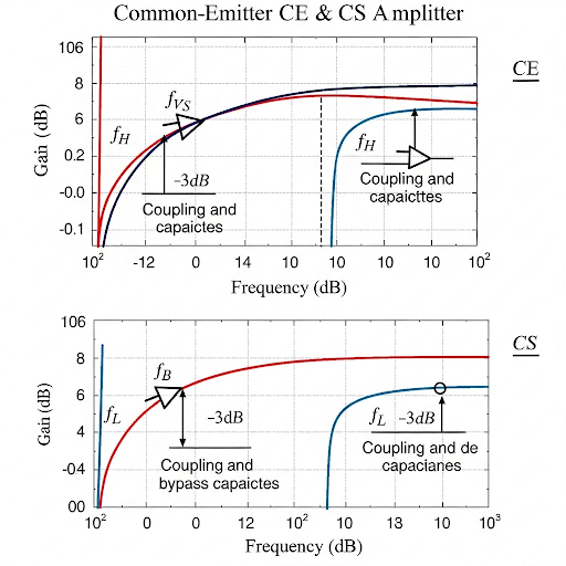
In this section, we explore the frequency response of CE and CS amplifiers, delving into the analysis of low and high-frequency behavior, the role of coupling capacitors, and the relationship between transfer functions and frequency response using RC and CR circuits.
Detailed
Detailed Summary
This section focuses on the frequency response of Analog Electronic Circuits, particularly Common Emitter (CE) and Common Source (CS) amplifiers. The discussion begins with an overview of the frequency response analysis of RC and CR circuits, allowing students to build a foundational understanding needed for more complex circuits. The significance of transfer functions in Laplace domain is emphasized, stressing how to derive frequency response from these functions by substituting variables.
The relationship between poles, zeros, and cutoff frequencies is also covered, providing insights into how the gain of the circuit varies with frequency as well as the expected phase shifts. Additionally, the significance of Bode plots in illustrating such relationships and behaviors is discussed, portraying how amplifiers behave at different frequency ranges, categorizing their performance into pass bands and stop bands. This section intends to equip learners with the knowledge necessary for further exploration of numerical analyses and design guidelines in subsequent lectures.
Youtube Videos

Audio Book
Dive deep into the subject with an immersive audiobook experience.
Introduction to Frequency Response
Chapter 1 of 7
🔒 Unlock Audio Chapter
Sign up and enroll to access the full audio experience
Chapter Content
Yeah, dear students welcome back to this NPTEL online program on Analog Electronic Circuits, myself Pradeep Mandal from the E and ECE Department of IIT Kharagpur. We are going through different modules and presently we are in the 4th module of this course. And, today’s topic of discussion it is Frequency Response of CE and CS Amplifier; Common Emitter and Common Source Amplifier.
Detailed Explanation
In this introductory section, Professor Pradeep Mandal welcomes students back to the course on Analog Electronic Circuits. He highlights that they are currently in the fourth module, focusing on the frequency response of two types of amplifiers: the Common Emitter (CE) and Common Source (CS) amplifiers. Frequency response refers to how the gain of these amplifiers changes with varying input signal frequency.
Examples & Analogies
Think of a speaker system: just like how speakers handle different frequencies differently (some may sound better with bass, while others handle treble well), amplifiers also respond differently to various signal frequencies. This section sets the stage for understanding how each type of amplifier manages frequency changes.
Review of Previous Topics
Chapter 2 of 7
🔒 Unlock Audio Chapter
Sign up and enroll to access the full audio experience
Chapter Content
In the previous module we have seen how to find the gain of common emitter and common source amplifier. And, today what we will see that if we change the frequency of the input signal how the gain of the circuit whether it is common emitter or common source amplifier, it is it changes with frequency.
Detailed Explanation
Here, the professor remarks on the learning from the previous module, where students learned to calculate the gain of CE and CS amplifiers. Now, they are going to explore how this gain varies when the frequency of the input signal changes. Understanding this relationship is crucial for designing circuits that perform reliably across different frequency ranges.
Examples & Analogies
Imagine tuning a guitar: as you press different frets, the pitch of the string changes. Similarly, as the frequency of input changes in an amplifier, the gain adjusts accordingly, much like how a musician must adjust their playing to capture different notes.
Plan for Today's Module
Chapter 3 of 7
🔒 Unlock Audio Chapter
Sign up and enroll to access the full audio experience
Chapter Content
Now, what do we have in this plan, in this module; it is the or rather today and the next classes are the following. So, we are planning to cover as I said that we are going to cover frequency response of common source and common emitter amplifier.
Detailed Explanation
In this chunk, the professor outlines the structure for today's lesson and the upcoming classes. He emphasizes that the main focus will be on the frequency response of both the common source and common emitter amplifiers. This gives students a clear understanding of what to expect in their learning.
Examples & Analogies
Think of this section like a syllabus for a class trip: it tells you where you will go, what you will learn, and the activities to expect. Just as you prepare for an exciting day out, students can prepare mentally for the topics ahead.
Understanding R-C and C-R Circuits
Chapter 4 of 7
🔒 Unlock Audio Chapter
Sign up and enroll to access the full audio experience
Chapter Content
To understand that first what we will do that we will revisit the frequency response of R-C circuit and C-R circuit. And, then based on the R-C and C-R circuit we will be talking about the transfer function of a typical system R-C or C-R combination.
Detailed Explanation
This part of the lecture explains that to grasp the frequency response of the amplifiers, the class will first revisit R-C (resistor-capacitor) and C-R (capacitor-resistor) circuits. The professor indicates that understanding these circuits is foundational for discussing the transfer functions, which describe how input signals are transformed into output signals in the circuit.
Examples & Analogies
Consider a water pipe system where water flow is regulated by a gate (resistor) and a storage tank (capacitor). Understanding how this setup works will help you appreciate how electrical signals are processed in amplifiers, similar to how water flows and fills the tank.
Transfer Function and Frequency Response
Chapter 5 of 7
🔒 Unlock Audio Chapter
Sign up and enroll to access the full audio experience
Chapter Content
And, then we will also discuss about what is the relationship between transfer function and then frequency response and then location of the pole zeroes in Bode in Laplace domain transfer function.
Detailed Explanation
In this segment, the professor mentions the discussion of the relationship between transfer functions and frequency responses. Transfer functions help determine how a circuit responds to different inputs. The locations of poles and zeros (specific points that affect the circuit’s response) in the transfer function, especially in Bode plots, will be examined.
Examples & Analogies
Think of taking a delivery route: the poles are like traffic lights that stop the flow of delivery at certain points, while zeros might represent shortcuts or points with no delay. Knowing these points helps optimize the delivery route, just as understanding poles and zeros helps engineers design better circuits.
Exploring the Frequency Response of Amplifiers
Chapter 6 of 7
🔒 Unlock Audio Chapter
Sign up and enroll to access the full audio experience
Chapter Content
So, and then what is the relationship between the pole and zeroes and the cut off frequency in the frequency response.
Detailed Explanation
The professor continues by linking the concepts of poles and zeros to the cutoff frequency in the frequency response. The cutoff frequency marks the point where the output begins to significantly drop compared to the input, which is critical for understanding amplifier behavior.
Examples & Analogies
Consider a filter in a pool that only allows certain sizes of debris to pass through while blocking larger items. The cutoff frequency is like the size limit—particles smaller than this can pass, while larger ones are trapped. Similarly, amplifiers allow certain signal frequencies to pass while attenuating others.
Frequency Response Analysis and Design Guidelines
Chapter 7 of 7
🔒 Unlock Audio Chapter
Sign up and enroll to access the full audio experience
Chapter Content
Then also we do have planned to cover design guidelines, once we once we recover the frequency response.
Detailed Explanation
Here, the professor highlights that they will also cover design guidelines after discussing the frequency response. These guidelines will help students understand how to design amplifiers that meet certain performance criteria related to frequency behavior.
Examples & Analogies
Designing an amplifier is akin to planning a nutrition plan—understanding which ingredients (resistors, capacitors) to include and in what amounts will help achieve the desired outcome (sound quality) just like the right balance of nutrients ensures good health.
Key Concepts
-
Frequency Response: The change in amplifier gain with varying input frequency.
-
Transfer Function: The mathematical representation of input-output relationships in circuits.
-
Cutoff Frequency: A critical frequency defining the transition from pass to stop band.
-
Bode Plot: A graphical representation comparing gain and phase against frequency on a logarithmic scale.
-
Poles and Zeros: Key points in transfer functions indicating circuit stability and response.
Examples & Applications
In an RC circuit, at low frequencies, the capacitor behaves like an open circuit, attenuating the input signal.
At the cutoff frequency, the output of a common emitter amplifier begins to drop significantly, indicating a change in behavior.
Memory Aids
Interactive tools to help you remember key concepts
Rhymes
Gain that’s high, when frequency is low,
Stories
Once upon a time in Circuit Land, the amplifier lived happily at low frequencies. But as the input signal became too powerful (in frequency), it was met with resistance and learned to adjust its gain—this was its cutoff point, transitioning between pass and stop band.
Memory Tools
Remember the acronym POLAR: Poles influence Over gain, Loss at cutoff, Amplifier's response changes, Reflect phase.
Acronyms
BODIES
Bode plots Offer Diagrams of Input and Output Signals.
Flash Cards
Glossary
- Amplifier
An electronic device that increases the power, voltage, or current of a signal.
- Bode Plot
A graphical plot that shows the magnitude and phase of an amplifier’s gain in relation to frequency.
- Cutoff Frequency
The frequency at which the output signal drops to a specific level, usually 3 dB below the maximum output.
- Poles and Zeros
Poles refer to the values of 's' that set the denominator of a transfer function to zero; zeros set the numerator to zero.
- Transfer Function
A mathematical representation of the relationship between the input and output signals in a system.
Reference links
Supplementary resources to enhance your learning experience.