
APPLICATION OF JUNCTION DIODE AS A RECTIFIER
Enroll to start learning
You’ve not yet enrolled in this course. Please enroll for free to listen to audio lessons, classroom podcasts and take practice test.
Interactive Audio Lesson
Listen to a student-teacher conversation explaining the topic in a relatable way.
Basics of Diode Functionality
🔒 Unlock Audio Lesson
Sign up and enroll to listen to this audio lesson

Good morning class! Today, we are discussing junction diodes and their application as rectifiers. Can anyone tell me what a diode does?

A diode only allows current to flow in one direction, right?
Exactly! This unidirectional property allows us to use diodes to convert alternating current or AC into direct current or DC. This process is called rectification. Can anyone explain what happens when the diode is forward biased?

The diode conducts when it’s forward biased.
Precisely! It conducts during the positive half-cycles of an AC signal. During the reverse bias, what happens?

It blocks the current, and no current flows.
Great! So, forward = conducting and reverse = blocking. To remember this, think of 'FORward' means 'Flow' and 'REVerse' means 'Restrict'.
Now, to summarize, a diode allows current during forward bias and blocks it during reverse. This is essential for rectification.
Half-Wave Rectification
🔒 Unlock Audio Lesson
Sign up and enroll to listen to this audio lesson

Let’s delve deeper into how diodes are used in a half-wave rectifier. Can anyone describe how a half-wave rectifier works?

It uses one diode to let current through during the positive cycle of AC.
Correct! During the negative cycle, the diode doesn’t conduct, effectively blocking the current. What do we observe at the load?
We get a pulsating DC output.
Exactly! The output waveform shows voltage spikes corresponding to the positive half-cycles. Can anyone summarize the advantages of this kind of rectification?
It's simple and requires only one diode!
That's a good point! However, what’s a limitation of a half-wave rectifier?
We only use half of the AC input, which is not very efficient.
Correct again! So remember: simple but not efficient. That's key.
Full-Wave Rectification
🔒 Unlock Audio Lesson
Sign up and enroll to listen to this audio lesson
Now, let's discuss full-wave rectification. Who can explain how a full-wave rectifier differs from a half-wave rectifier?
It uses two diodes, allowing current to flow from both halves of the AC cycle.
Exactly! This means we can use both positive and negative halves of the input signal. What is a common type of circuit used for full-wave rectification?
A bridge rectifier!
Correct! A bridge rectifier uses four diodes arranged in a square. Now, let’s explore the significance of using full-wave rectification. What is one advantage?
It produces smoother output because it utilizes both halves of the wave.
Absolutely! More efficiency and less ripple in the output. Remember, 'full-wave' = 'full use of AC'.
Smoothing Pulsating Output
🔒 Unlock Audio Lesson
Sign up and enroll to listen to this audio lesson
To smooth out the pulsating DC we obtain from our rectifiers, we introduce filters. Can someone tell me what component is commonly used for filtering?
Capacitors!
That's right! Capacitors help store and release charge, thus smoothing the output. Summarize for me how a capacitor functions in this setup.
It charges when the voltage is high and discharges when the voltage is low.
Exactly! This charging and discharging create a more stable DC output. For retention, think of 'CAPacitor = CArefully At Peak'.
So the capacitor smooths out the voltage variations. Let's summarize everything we’ve discussed about diodes and rectification.
Recap and Questions
🔒 Unlock Audio Lesson
Sign up and enroll to listen to this audio lesson
Let's recap what we've learned today about junction diodes and their applications as rectifiers. What are the key functions of a diode?
It conducts current in one direction and blocks it in another.
Correct! And what did we say about the difference between half-wave and full-wave rectification?
Half-wave uses one diode and only conducts during one half of the cycle, while full-wave uses multiple diodes to conduct during both halves.
Exactly! And how do we smooth out the output voltage?
By using capacitors as filters!
Great job! Now, do you have any questions about the section?
Introduction & Overview
Read summaries of the section's main ideas at different levels of detail.
Quick Overview
Standard
In this section, we explore the operation of junction diodes in rectification. It explains two types of rectifiers—half-wave and full-wave—and their configurations. The section illustrates how the diode allows current during forward bias and blocks it during reverse bias, resulting in a pulsating output voltage converted to DC using capacitors and filters.
Detailed
Detailed Summary
Junction diodes are fundamental components in electronic circuits, primarily used for rectification. This section highlights the behavior of junction diodes under varying bias conditions.
- Diode Behavior: A junction diode permits current to pass only when forward biased, effectively allowing current flow during one half of an alternating current (AC) cycle. This characteristic is leveraged to rectify AC into direct current (DC).
- Half-Wave Rectifiers: The simplest configuration uses a single diode to rectify AC. In a half-wave rectifier, the diode conducts during the positive half-cycle of input AC while blocking the negative half-cycle, resulting in a pulsating DC output. The diode's reverse saturation current is minimal, approximating zero for practical purposes.
- Full-Wave Rectifiers: A full-wave rectifier employs two diodes or a bridge circuit, making use of both halves of the AC wave. This circuit configuration not only increases efficiency but also provides a smoother output. Each diode conducts during alternate cycles, ensuring continuous rectification.
- Filtering: To convert the pulsating output into a steady DC voltage, capacitors are added to the output. These capacitors charge when voltage peaks and discharge when the voltage drops, effectively smoothing the output voltage waveform.
In summary, junction diodes serve a critical function in power supply circuits, allowing for efficient conversion of AC to DC while being foundational in semiconductor electronics.
Youtube Videos


Audio Book
Dive deep into the subject with an immersive audiobook experience.
Diode Forward Bias and Current Flow
Chapter 1 of 4
🔒 Unlock Audio Chapter
Sign up and enroll to access the full audio experience
Chapter Content
From the V-I characteristic of a junction diode we see that it allows current to pass only when it is forward biased. So if an alternating voltage is applied across a diode, the current flows only in that part of the cycle when the diode is forward biased. This property is used to rectify alternating voltages and the circuit used for this purpose is called a rectifier.
Detailed Explanation
A junction diode is a device that allows current to pass through it only in one direction when it is forward biased. When connected to an alternating voltage source, the diode only conducts during the positive half of the alternating current (AC) cycle. This selective conduction enables the conversion of AC, which varies in direction, into direct current (DC), which flows in one direction.
Examples & Analogies
Think of a one-way street sign that allows cars to go in one direction but blocks them from coming back. In the same way, a diode only allows current to flow when it's in the designated direction (forward bias), effectively converting the fluctuating traffic of AC electricity into a steady flow of DC electricity.
Half-Wave Rectification
Chapter 2 of 4
🔒 Unlock Audio Chapter
Sign up and enroll to access the full audio experience
Chapter Content
If an alternating voltage is applied across a diode in series with a load, a pulsating voltage will appear across the load only during the half cycles of the ac input during which the diode is forward biased. Such rectifier circuit, as shown in Fig. 14.18, is called a half-wave rectifier.
Detailed Explanation
In a half-wave rectifier circuit, the alternating voltage is applied to the diode and load resistor. When the AC input voltage is positive, the diode becomes forward biased and current flows through the load. However, when the AC input voltage becomes negative, the diode is reverse biased and stops the current. This results in a pulsating output voltage that only includes the positive half of the input signal.
Examples & Analogies
Imagine a water pump that only allows water to flow when you push down on a lever. When you release the lever, the pump stops letting any water through. Similarly, a half-wave rectifier only allows electrical 'flow' (current) during the positive part of the AC cycle.
Full-Wave Rectification
Chapter 3 of 4
🔒 Unlock Audio Chapter
Sign up and enroll to access the full audio experience
Chapter Content
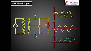
The circuit using two diodes, shown in Fig. 14.19(a), gives output rectified voltage corresponding to both the positive as well as negative half of the ac cycle. Hence, it is known as full-wave rectifier.
Detailed Explanation
A full-wave rectifier utilizes two diodes to conduct during both halves of the AC cycle. By arranging the diodes to alternate their conduction based on the AC input, both the positive and negative halves are converted into a pulsating DC output. This configuration results in a higher average output voltage compared to a half-wave rectifier.
Examples & Analogies
Think of a seesaw with two people on either end. When one side goes up (positive cycle), the person on the other end goes down (negative cycle). If both people can push off the ground at the same time, they can create a smoother ride. In the full-wave rectifier, both sides of the AC wave create a smoother and more consistent DC output.
Capacitors in Rectifier Circuits
Chapter 4 of 4
🔒 Unlock Audio Chapter
Sign up and enroll to access the full audio experience
Chapter Content
To get steady dc output from the pulsating voltage normally a capacitor is connected across the output terminals (parallel to the load R).
Detailed Explanation
A capacitor is used in rectifier circuits to smooth out the pulsating voltage by charging up when the voltage rises and discharging when the voltage falls. This ability to fill in the dips in voltage leads to a more stable and steady DC output.
Examples & Analogies
Imagine a sponge soaked in water. As you pour water (the pulsating voltage) onto it, the sponge absorbs the excess and releases it slowly, keeping the output flow more steady. Similarly, in a circuit, the capacitor stores energy and releases it to maintain a more constant voltage.
Key Concepts
-
Unidirectional behavior of diodes: Diodes permit current flow in one direction only, crucial for rectification.
-
Half-Wave Rectification: Uses a single diode, allowing current only during the positive half-cycle of AC.
-
Full-Wave Rectification: Utilizes both halves of the AC signal, providing more efficient output through multiple diodes.
-
Filtering: The process of smoothing pulsating DC signals through capacitors to attain steadier output.
Examples & Applications
A diode connected to an AC circuit allows current during the positive half cycles, resulting in a pulsating DC.
In a full-wave rectifier setup with a bridge circuit, both halves of the AC input are used, producing a smoother output voltage.
Memory Aids
Interactive tools to help you remember key concepts
Rhymes
When the current flows one way, the diode leads the way!
Stories
Imagine a traffic light where diodes only let cars go in one direction. They stop all traffic from the other direction!
Memory Tools
For Half-Wave, think ONE: One cycle, One diode!
Acronyms
CAP stands for Capacitors Aid Pulsating current to become stable.
Flash Cards
Glossary
- Junction Diode
A semiconductor device that allows current to flow in one direction only.
- Rectification
The process of converting AC to DC using a diode.
- HalfWave Rectifier
A circuit that allows current to flow only during the positive half-cycles of AC.
- FullWave Rectifier
A circuit that converts both halves of AC to DC, utilizing more efficient diode arrangements.
- Filtering
The process by which fluctuation in the output voltage is smoothed, typically using capacitors.
Reference links
Supplementary resources to enhance your learning experience.