
Proficiency in Verilog
Interactive Audio Lesson
Listen to a student-teacher conversation explaining the topic in a relatable way.
Basic Syntax and Structure of Verilog
🔒 Unlock Audio Lesson
Sign up and enroll to listen to this audio lesson

Today, we are going to discuss Verilog. Can anyone tell me what makes Verilog a popular hardware description language?

I think it's the simplicity of its syntax, which makes coding easier.
Absolutely! Verilog is known for its concise syntax. This helps in writing code faster. Now, does anyone know the key design principles of Verilog?

It supports both behavioral and structural forms of design.
Great point! This versatility allows Verilog to be used in a variety of applications. Remember the acronym 'B-S' for Behavioral and Structural designs. Let's move on to a practical example. Can someone tell me what a 4-bit counter in Verilog might look like?

It would include a counter that increments its value on every clock pulse.
Correct! A 4-bit counter would count from 0 to 15. To sum up today's session, Verilog's basic syntax emphasizes simplicity and efficiency in coding digital systems.
Verilog in FPGA and ASIC Design
🔒 Unlock Audio Lesson
Sign up and enroll to listen to this audio lesson

Now that we understand Verilog's syntax, let's discuss its application in FPGA and ASIC design. Why is Verilog preferred for such environments?

I think it’s because Verilog allows efficient resource usage, especially on FPGAs.
Exactly! It's crucial to manage resources effectively to meet design constraints. So, what are some design considerations we need to keep in mind for FPGA projects?
Timing is super important, especially how we model clock domains.
Spot on! Ensuring proper clock synchronization can save us from significant issues. Let's consider a project to design a 16-bit parallel adder. What could be the steps involved?
We’d start by defining the inputs and outputs, then implement the addition logic.
Great! A strong final point is to always verify timing constraints during implementation to ensure performance. Always keep in mind the 'P-C' acronym for Performance and Constraints.
Introduction & Overview
Read summaries of the section's main ideas at different levels of detail.
Quick Overview
Standard
In this section, we delve into the proficiency in Verilog, detailing its basic syntax, design principles, and key applications, particularly in FPGA and ASIC designs. It highlights the advantages of Verilog's conciseness and versatility in digital circuit simulation and synthesis.
Detailed
Proficiency in Verilog
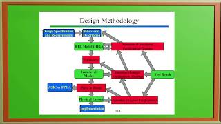
Verilog is a fundamental hardware description language (HDL) widely used in the design and simulation of digital circuits. Known for its simplicity and efficacy, Verilog provides a straightforward syntax that caters to both behavioral and structural modeling. This section outlines crucial aspects of Verilog proficiency, emphasizing design principles that characterize this language.
Basic Syntax and Structure
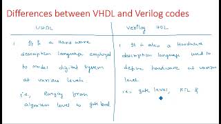
Verilog employs a less verbose syntax compared to its counterpart VHDL, which enhances programming efficiency. Verilog supports various design styles, enabling designers to express complex circuit functionality efficiently, making it particularly useful for large-scale designs such as microprocessors and memory systems. Examples include creating simple components like a 4-bit counter, which can be tested in simulation environments such as ModelSim or XSIM.
Practical Applications
Verilog's powerful capabilities extend to FPGA and ASIC design, focusing on the efficient utilization of hardware resources. Design considerations in this context include resource management for FPGAs and accurately modeling clock domains to avoid synchronization issues. A hands-on project example is the design of a 16-bit parallel adder in Verilog with an emphasis on proper timing constraints and performance verification.
In summary, proficiency in Verilog involves understanding its unique syntax, recognizing its structural and behavioral design capabilities, and effectively applying it in FPGA and ASIC environments.
Youtube Videos

Audio Book
Dive deep into the subject with an immersive audiobook experience.
Basic Syntax and Structure
Chapter 1 of 4
🔒 Unlock Audio Chapter
Sign up and enroll to access the full audio experience
Chapter Content
Verilog is a hardware description language that focuses on simplicity and conciseness. It is widely used for both simulation and synthesis of digital circuits.
● Design Principles:
○ Verilog supports both behavioral and structural design styles.
○ It is less verbose compared to VHDL, making it faster for designers to write and debug code.
○ Verilog is widely adopted in the industry, particularly for large-scale designs such as processors and memory systems.
Detailed Explanation
This chunk introduces Verilog as a hardware description language (HDL) known for its straightforwardness and compactness. Unlike other languages that may require longer expressions, Verilog allows designers to describe digital circuits in fewer lines of code, enhancing productivity. The mention of both behavioral and structural design implies that designers can either describe how a circuit behaves (behavioral) or how it's built (structural). This flexibility is a key advantage in various applications, particularly for large projects like designing processors or memory systems, where efficiency is vital.
Examples & Analogies
Think of Verilog like writing a recipe. A simpler recipe can be quicker and easier to follow, just as Verilog code is easier to write and understand compared to more elaborate programming methods. If you were making a simple dish, you might have a straightforward list of ingredients and steps—like in Verilog—while a more complex dish might have a lengthy, detailed process that could resemble a more verbose HDL.
Project Work Example: 4-Bit Counter
Chapter 2 of 4
🔒 Unlock Audio Chapter
Sign up and enroll to access the full audio experience
Chapter Content
Create a simple 4-bit counter in Verilog and test its functionality in a simulation environment like ModelSim or XSIM.
Detailed Explanation
This project example illustrates a practical application of Verilog, where students can create a 4-bit counter. A 4-bit counter counts from 0 to 15 in binary. By testing its functionality using simulation tools like ModelSim or XSIM, students can verify that their design works as expected before physical implementation. Using a simulation environment allows students to observe how the counter behaves over time and ensure it meets the desired specifications.
Examples & Analogies
Imagine a digital clock that counts the seconds. Just like you’d want to verify if a clock ticks properly from 00:00 to 00:59, students can simulate their 4-bit counter to ensure it counts accurately without actually building the hardware. This way, they can catch any mistakes in their design without spending time and resources on physical components.
Verilog in FPGA and ASIC Design
Chapter 3 of 4
🔒 Unlock Audio Chapter
Sign up and enroll to access the full audio experience
Chapter Content
Verilog is used in both FPGA design and ASIC development due to its concise syntax and powerful simulation capabilities.
● Design Considerations:
○ Focus on efficient resource usage, especially when working with FPGA hardware.
○ Correctly model clock domains and synchronization when designing complex systems.
Detailed Explanation
This chunk emphasizes the relevance of Verilog in two key areas: FPGA design and ASIC development. FPGAs and ASICs are types of hardware used in digital circuits, and Verilog's concise syntax is particularly beneficial for developers focusing on efficient use of resources. Additionally, the need to correctly model clock domains and synchronization highlights the importance of timing in digital circuits. Poor timing can lead to errors, so understanding how to handle these aspects is crucial for successful hardware design.
Examples & Analogies
Consider Verilog as a tool that helps you plan and build a bridge. In bridge construction (FPGA and ASIC design), you must use materials efficiently and ensure that parts of the bridge (like the lanes or supports) work together harmoniously (synchronization). If one part is off, it could lead to the whole bridge not functioning correctly—just like how precise timing is essential for circuits to work effectively.
Project Work Example: 16-Bit Parallel Adder
Chapter 4 of 4
🔒 Unlock Audio Chapter
Sign up and enroll to access the full audio experience
Chapter Content
Design a 16-bit parallel adder in Verilog and implement it on an FPGA. Ensure proper timing constraints and verify performance.
Detailed Explanation
This project introduces a 16-bit parallel adder, a fundamental digital circuit that adds binary numbers using multiple bits simultaneously. Implementing the design on an FPGA enables students to create a functional hardware circuit that performs addition in real-time. They must pay particular attention to timing constraints to ensure the circuit operates correctly. In digital systems, timing is vital; therefore, verifying performance is a necessary step to validate the functionality of the adder.
Examples & Analogies
Think of the adder as a team of people adding up scores in a game. If they are working together in parallel (like a parallel adder), they can sum scores much faster than if they did it one at a time. However, everyone needs to agree on the rules (timing constraints) to ensure they all finish at the same moment; otherwise, some scores won't count correctly—similar to how precise timing is crucial in digital circuits to avoid errors.
Key Concepts
-
Verilog's Syntax: Verilog uses a concise syntax that enhances coding efficiency.
-
Behavioral and Structural Design: Verilog supports both design styles, allowing flexibility in modeling.
-
FPGA and ASIC Design: Verilog is widely used in FPGA and ASIC projects, emphasizing resource management.
Examples & Applications
A 4-bit counter in Verilog counts from 0 to 15 based on clock pulses.
A 16-bit parallel adder implementation may utilize Verilog's concise syntax to manage carry bits effectively.
Memory Aids
Interactive tools to help you remember key concepts
Rhymes
In Verilog, write it quick, simple syntax, that's the trick.
Stories
Think of Verilog as a friendly guide in the land of digital design, helping you build circuits with ease, just like building blocks in a playground.
Memory Tools
Remember 'B-S' for Behavior and Structure when using Verilog.
Acronyms
Use 'P-C' for Performance and Constraints in Verilog designs.
Flash Cards
Glossary
- Verilog
A hardware description language used for modeling, simulating, and synthesizing digital circuits.
- FPGA
Field-Programmable Gate Array, a type of hardware that can be programmed to perform specific tasks.
- ASIC
Application-Specific Integrated Circuit, a customized circuit designed for a particular application.
Reference links
Supplementary resources to enhance your learning experience.