
Introduction to Pipe Systems Design
Enroll to start learning
You’ve not yet enrolled in this course. Please enroll for free to listen to audio lessons, classroom podcasts and take practice test.
Interactive Audio Lesson
Listen to a student-teacher conversation explaining the topic in a relatable way.
Introduction to Pipe Systems
🔒 Unlock Audio Lesson
Sign up and enroll to listen to this audio lesson

Let's start with the basics of pipe systems. Can anyone tell me what constitutes a water supply system?

I think it includes the source of water and the network of pipes that distribute it.
Exactly, well done! The source could be a reservoir or a treatment plant, and the network connects to different locations. It's crucial to understand that this network can be very complex.

What kind of issues should we consider when designing these systems?
Great question! One major issue is energy loss. Can anyone tell me what that means in the context of fluid flow?

I think it's about how much energy is lost as water flows through the pipes.
Correct! Energy loss in flow can be quantified by head loss, which relies on Bernoulli’s equation. Let's remember that principle as we’ll return to it later.
Energy Losses and Head Loss
🔒 Unlock Audio Lesson
Sign up and enroll to listen to this audio lesson

Now that we have a foundation, let's discuss energy losses further. Why do you think head loss is an important factor?

Maybe because it affects how efficiently the system can move water?
Exactly! Higher head loss means less energy is available for flow, which can lead to inadequate water supply. Can anyone explain how we measure this loss?
By using Bernoulli’s equation and other formulas, right?
Yes, and the Darcy-Weisbach formula specifically helps in calculating head loss based on flow velocity and friction factors. Remember, we want smooth pipe systems to reduce energy loss!
What about turbulent flow? How does that come into play?
Good point! Turbulent flow generates more energy loss due to friction. Understanding these flows is key to effective system design.
Dimensional Analysis and Turbulent Flow
🔒 Unlock Audio Lesson
Sign up and enroll to listen to this audio lesson
Let’s dive deeper into turbulent flow and how it affects our designs. Can someone remind me what factors influence pressure drop along a pipe?
Factors like pipe diameter, length, viscosity, and average velocity?
Precisely! These factors play critical roles in dimensional analysis. What do we consider to reduce turbulence?
Having smoother pipes or optimizing the flow velocity could help, right?
Exactly! Smoother internal surfaces reduce roughness, which is vital for maintaining efficiency in the system.
I remember you mentioning the Reynolds number earlier. What's its significance?
Great recall! The Reynolds number helps us determine whether the flow is laminar or turbulent, aiding in our design choices.
Introduction & Overview
Read summaries of the section's main ideas at different levels of detail.
Quick Overview
Standard
In this section, key aspects of pipe systems design are discussed, including the identification of energy losses in water supply systems and the application of Bernoulli's equations. The impact of pipe roughness on turbulence and energy dissipation is also highlighted, emphasizing its importance in the overall design process.
Detailed
Detailed Summary
This section extensively explores the design of pipe systems, particularly within the context of water supply systems. It begins with the basics of how these systems are structured, focusing on the sources and networks of pipes that distribute water to various locations. A critical aspect discussed is the energy losses associated with fluid flow, emphasizing the concept of head loss, which is derived from Bernoulli’s equations.
The section underscores the need to quantify energy availability throughout the pipe network to understand flow dynamics. Turbulent flow is particularly highlighted as a crucial factor in understanding energy losses, with discussions on dimensional analysis and the governing variables that influence these losses, such as pipe diameter, length, and the roughness characteristics of the pipe materials.
Students are introduced to concepts like the Darcy-Weisbach equation for head loss, detailing how friction factors vary with Reynolds numbers and relative roughness. The section incorporates experimental findings, such as those from Nikuradse, to illustrate how these factors interact in real-world scenarios, emphasizing the significance of conducting experiments to determine friction factors and energy loss in pipe flows.
Youtube Videos


Audio Book
Dive deep into the subject with an immersive audiobook experience.
Overview of Pipe Systems
Chapter 1 of 9
🔒 Unlock Audio Chapter
Sign up and enroll to access the full audio experience
Chapter Content
So what they did is that to design these pipe systems like for examples, we have a water supply systems, okay. So if you have a water supply systems, there could be a source and there could be the pipe network to different locations. There will be you can imagine it that can have a very complex pipe networks supplying to water to different locations. How to design these pipe networks.
Detailed Explanation
Pipe systems are essential for distributing water from a source to various locations. This involves creating a network of pipes that can be complex, with various branches leading to different areas. Understanding how to design these networks effectively is key to ensuring efficient water delivery.
Examples & Analogies
Think of a city's water supply system like a tree. The main trunk of the tree represents the main pipe leading from the water source, while the branches represent smaller pipes that distribute the water to different neighborhoods.
Understanding Energy Losses
Chapter 2 of 9
🔒 Unlock Audio Chapter
Sign up and enroll to access the full audio experience
Chapter Content
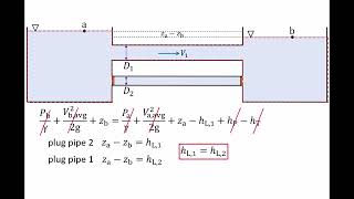
So now it is coming it that we can find out how much energy losses, how the head losses in the pipe flow systems. You can know how much energy loss is here, how much of energy loss is here, then I can quantify the energy availability at different parts. That energy availability will give us the flow is coming or not coming.
Detailed Explanation
In designing pipe systems, it's crucial to calculate the energy and head losses that occur due to friction and other factors. Accurately quantifying these energy losses helps determine whether adequate water flow can be maintained at different parts of the system.
Examples & Analogies
Imagine you're trying to push water through a long garden hose. If the hose is too narrow or has kinks, it's harder for the water to flow, similar to how friction in pipes can restrict water movement.
Analogy to Electrical Power Transmission
Chapter 3 of 9
🔒 Unlock Audio Chapter
Sign up and enroll to access the full audio experience
Chapter Content
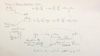
This is quite analogous to your power transmissions, electrical power transmissions like similar way. But here we are talking about the head losses the energy losses in a pipe network or in pipe flow.
Detailed Explanation
The principles used in designing pipe systems for fluids can be compared to those used in electrical power transmission. Both systems have to account for losses—in pipe systems, we call this head loss, while in electrical systems, we deal with voltage drop. Understanding these losses is essential for efficient system design.
Examples & Analogies
Just as electricity loses voltage as it travels along wires, water loses pressure as it flows through pipes, especially if they are long or narrow. Both need to be carefully managed to ensure the systems work efficiently.
Conducting Experiments to Quantify Losses
Chapter 4 of 9
🔒 Unlock Audio Chapter
Sign up and enroll to access the full audio experience
Chapter Content
So we need to do the experiment to quantify energy losses and that in terms of head loss. That means in terms of Bernoulli’s equations point of view we are talking about head loss. But we are looking at what will be the energy loss part.
Detailed Explanation
Conducting experiments is vital to understand and quantify the energy losses in pipe systems. By using Bernoulli's equations, we can derive relationships that help describe how these losses impact the overall flow and performance of the system.
Examples & Analogies
Think of it like testing different-sized straws in a drink. By measuring how much harder you have to suck to get the same amount of liquid through each straw, you can understand how different sizes affect flow—just like how experiments help us understand energy losses in pipes.
Dimensional Analysis of Pipe Flow
Chapter 5 of 9
🔒 Unlock Audio Chapter
Sign up and enroll to access the full audio experience
Chapter Content
Now let us now what we are doing it first the dimensional analysis. So if there is a pressure drop along a pipe in a turbulent flow depends upon the following quantities: Pipe diameters, length of the pipe, the coefficient of viscosity, average velocity, and small e represents the average variations in pipe radius.
Detailed Explanation
When analyzing flow in a pipe, factors such as pipe diameter, length, fluid viscosity, and average velocity play critical roles. Dimensional analysis helps establish relationships between these variables that can predict how they influence pressure drops in turbulent flows.
Examples & Analogies
It’s similar to how the width and length of a water slide determine how fast someone can slide down. The wider and smoother the slide (like a larger diameter and lower viscosity), the faster the water or person can move.
Influence of Pipe Roughness
Chapter 6 of 9
🔒 Unlock Audio Chapter
Sign up and enroll to access the full audio experience
Chapter Content
If you look at the pipe, different pipes will have different roughness like this glass surface maybe looks smooth but if you look microscopically there is a roughness. If you have a roughness in the pipes, then you have a more problems behavior happens it. More energy dissipates, less the energy dissipates. Smooth pipes result in less turbulence behavior.
Detailed Explanation
The roughness of pipe surfaces has a significant impact on flow behavior. While a pipe may appear smooth to the naked eye, microscopic roughness can cause turbulence, resulting in increased energy loss. Therefore, smoother pipes are more efficient as they experience less resistance.
Examples & Analogies
Consider the difference in speed between sliding down a polished slide versus a rough one. A smoother surface allows for faster, easier movement, just like smoother pipes allow for better fluid flow.
Dimensional Analysis and Friction Factors
Chapter 7 of 9
🔒 Unlock Audio Chapter
Sign up and enroll to access the full audio experience
Chapter Content
If you conduct a dimensional analysis, this is a non-dimensional path. The dependent variable non-dimensional form we got it where the Reynolds numbers, the dimensions or geometry of the pipe length and the diameters and this is with respect to the roughness height and the D.
Detailed Explanation
Through dimensional analysis, we can simplify complex systems into non-dimensional forms that relate key variables such as the Reynolds number, pipe geometry, and roughness. Understanding these relationships allows engineers to predict flow behavior without complicated calculations for every scenario.
Examples & Analogies
It’s like using a recipe that requires cups and teaspoons. By converting all measurements to just one standard (like grams), you simplify the cooking process and make it easier to replicate the recipe.
Head Loss and Darcy-Weisbach Formula
Chapter 8 of 9
🔒 Unlock Audio Chapter
Sign up and enroll to access the full audio experience
Chapter Content
The head loss will be proportional to the kinetic energy per unit mass, length over diameter ratio, and friction factor, which is a function of Reynolds numbers and roughness height to diameter ratio.
Detailed Explanation
The Darcy-Weisbach formula provides a way to calculate head loss in a pipe system. This loss is influenced by kinetic energy, pipe geometry, and the friction factor, which varies based on the flow conditions and pipe's surface roughness. Understanding this formula is critical for effective pipe system design.
Examples & Analogies
Imagine you are riding a bike. If you're riding uphill (like experiencing head loss), your speed and energy must increase to maintain the same pace. The slope (analogous to pipe diameter and length) affects how much effort is needed, similar to how the Darcy-Weisbach formula calculates energy needs in a pipe.
Experimental Data and Friction Factors
Chapter 9 of 9
🔒 Unlock Audio Chapter
Sign up and enroll to access the full audio experience
Chapter Content
We also discussed the experimental relationship between friction factors as a function of Reynolds numbers and relative roughness, and that is what is Moody’s chart for commercial pipes, Nikuradse’s chart for the artificially roughened pipe.
Detailed Explanation
Experimental studies, such as those represented by Moody's chart and Nikuradse's data, have established the relationship between friction factors, Reynolds numbers, and pipe roughness. These charts are valuable tools for engineers to quickly determine friction factors based on system parameters.
Examples & Analogies
Think of Moody's chart as a quick-reference guide, similar to a speed limit sign on a road. Just as the sign tells you how fast you can go based on road conditions, Moody's chart tells you the friction factor based on pipe conditions.
Key Concepts
-
Pipe Network: A system of pipes connecting water sources to delivery points, requiring careful design to manage flow and energy loss.
-
Energy Loss: The reduction in energy available for flow due to friction and turbulence, critical for maintaining efficiency in pipe systems.
-
Turbulent Flow: A chaotic flow regime that increases energy losses; understanding this is essential in design.
-
Head Loss: A measurement of physical energy lost due to friction, impacting flow effectiveness.
-
Friction Factor: A parameter calculated to evaluate resistance in flow, influenced by Reynolds number and pipe roughness.
Examples & Applications
In a smooth pipe system, energy loss due to friction is lower, allowing water to flow more efficiently compared to a rough pipe.
Using the Darcy-Weisbach equation, engineers can calculate the expected head loss for various pipe sizes and materials in design scenarios.
Memory Aids
Interactive tools to help you remember key concepts
Rhymes
Friction in pipes can lead to strife, it steals the flow, affecting life.
Stories
Imagine a river flowing over smooth stones versus rough rocks; the rough path slows the flow and makes it harder for fish to swim through – much like how rough pipes slow water movement due to friction.
Memory Tools
Use the acronym 'HEAD' to remember factors influencing head loss: H – Height changes, E – Energy dynamics, A – Area of flow, D – Diameter of pipes.
Acronyms
TURB for Turbulent flow understanding
– Turbulence
– Unsteady
– Rough surfaces
– Bad for energy efficiency.
Flash Cards
Glossary
- Head Loss
The loss of energy due to friction and turbulence as fluid flows through a pipe.
- Bernoulli's Equation
A principle that describes the behavior of fluid flow, illustrating the conservation of energy within the flow.
- Turbulent Flow
A type of fluid flow characterized by chaotic and irregular motion, often leading to increased energy loss.
- Friction Factor
A dimensionless number representing the resistance to flow due to friction in a pipe.
- DarcyWeisbach Equation
An equation used to calculate the head loss due to friction in a pipe.
Reference links
Supplementary resources to enhance your learning experience.