
Factors Affecting Energy Losses
Enroll to start learning
You’ve not yet enrolled in this course. Please enroll for free to listen to audio lessons, classroom podcasts and take practice test.
Interactive Audio Lesson
Listen to a student-teacher conversation explaining the topic in a relatable way.
Introduction to Energy Losses
🔒 Unlock Audio Lesson
Sign up and enroll to listen to this audio lesson

Today, we're discussing energy losses in pipe systems, particularly how head losses affect flow. Can anyone explain what head loss refers to?

Is it the energy lost when water flows through a pipe?
Exactly! Head loss can be seen as the energy dissipated due to frictional forces while the fluid moves through the pipe. Remember, more friction means more energy loss. Think of it as resistance in electrical circuits.

Are there specific factors that affect how much energy is lost?
Great question! Factors include pipe diameter, length, and surface roughness, all of which contribute to turbulence. Let's pay attention to how this turbulence plays a significant role in our calculations.

Can you summarize the importance of head loss again?
Sure! Head loss is crucial for determining how efficiently a system can transport water. It helps us design efficient plumbing and water delivery systems.
Understanding Pipe Characteristics
🔒 Unlock Audio Lesson
Sign up and enroll to listen to this audio lesson

Let's delve into how pipe dimensions affect energy losses. What role does the diameter of a pipe play?

A larger diameter would mean lower resistance, so less energy is lost, right?
Exactly! A larger diameter reduces the fluid's velocity, which decreases turbulence and, hence, energy losses. Now consider the length of the pipe—how does that affect our calculations?
A longer pipe would increase energy loss because there's more surface area for friction.
Correct! More length means more head loss due to friction. What about the material or surface roughness of the pipe?
If the pipe is rough, won’t that create more turbulence and increase energy losses?
Yes! Pipe roughness significantly impacts how smoothly the fluid flows. The smoother the pipe, the less energy is lost.
Friction Factors and Turbulence
🔒 Unlock Audio Lesson
Sign up and enroll to listen to this audio lesson
Now let's discuss friction factors. These factors are influenced by both Reynolds numbers and the relative roughness of the pipe. Can anyone explain Reynolds numbers?
Is it a dimensionless number that helps predict flow patterns? Like if the flow is laminar or turbulent?
Exactly! The Reynolds number helps us identify flow characteristics. A higher Reynolds number indicates a turbulent flow, while lower values suggest laminar flow. How do friction factors relate to this?
Higher friction factors mean higher energy losses in turbulent conditions, right?
You've got it! The friction factor varies with flow conditions and pipe roughness, impacting our calculations of head loss.
Can you provide a brief overview on calculating energy losses again?
Of course! Head loss is determined through the Darcy-Weisbach equation, using the friction factor, pipe length, and velocity. Always remember: energy losses are key to efficient system design!
Introduction & Overview
Read summaries of the section's main ideas at different levels of detail.
Quick Overview
Standard
The section discusses how energy losses in pipe systems, analogous to electrical power transmission, can be quantified using the analysis of head losses. It highlights factors like pipe diameter, length, viscosity, and surface roughness, and how they influence energy dissipation during turbulent flow.
Detailed
Factors Affecting Energy Losses
In hydraulic systems, particularly water supply networks, energy losses occur due to head losses across the pipe flow systems. Understanding how to quantify these energy losses is crucial for effective system design. This section draws parallels between fluid dynamics in pipes and electrical power transmission to highlight the importance of energy quantification at various points within a pipe network.
Key Concepts Discussed:
- Head Loss: Energy loss in pipe flow due to factors such as friction and turbulence.
- Turbulent Flow Analysis: The complexity of turbulent flow makes dimensional analysis necessary. Key variables include pipe diameter, length, viscosity, and flow velocity.
- Pipe Roughness: The microscopic roughness of pipe interiors affects turbulence levels, influencing energy loss.
The section concludes with explanations of friction factors, derived experimentally, that relate to pipe characteristics and turbulent flow conditions.
Youtube Videos


Audio Book
Dive deep into the subject with an immersive audiobook experience.
Understanding Pipe Systems and Energy Losses
Chapter 1 of 6
🔒 Unlock Audio Chapter
Sign up and enroll to access the full audio experience
Chapter Content
To design pipe systems, like a water supply network, we can identify the energy losses along the flow through the pipes. This involves quantifying head losses in the pipe flow systems to understand energy availability at different parts of the network.
Detailed Explanation
This chunk introduces the concept of pipe systems, especially focusing on water supply networks. The initial step in designing these systems is to determine how much energy is lost as water flows through, referred to as head losses. These losses occur due to the friction of water against the pipe walls and other factors like turbulence. By quantifying these losses, engineers can determine if there is enough energy for the water to flow effectively.
Examples & Analogies
Imagine a city’s water supply system as a system of highways. Just like cars face slowdowns or energy loss due to traffic, water faces similar energy losses when it flows through pipes. If there are too many curves and bumps in the road (akin to friction in pipes), water might not reach its destination efficiently.
Turbulent Flow and Governing Variables
Chapter 2 of 6
🔒 Unlock Audio Chapter
Sign up and enroll to access the full audio experience
Chapter Content
In turbulent flow through pipe systems, we consider dependent variables like average pressure, velocity, and pipe characteristics. Simplifications such as neglecting hydrostatic variations help focus on the average conditions during a fully developed steady flow.
Detailed Explanation
Turbulent flow is complex, but engineers simplify the analysis by focusing on average pressure and velocity rather than their instantaneous values. This means looking at how water behaves on average over time, allowing engineers to apply models like the Bernoulli equation more effectively. In steady flow, variations in pressure due to height (hydrostatics) can often be ignored, simplifying calculations.
Examples & Analogies
Think of a busy restaurant kitchen. Instead of observing each chef in real-time, a manager might look at the average time taken to prepare a dish during rush hours to assess efficiency. Similarly, in turbulent flow analysis, we consider average conditions to get a clearer picture.
Dimensional Analysis in Pipe Flow
Chapter 3 of 6
🔒 Unlock Audio Chapter
Sign up and enroll to access the full audio experience
Chapter Content
The pressure drop in turbulent flow is influenced by factors like pipe diameter, length, viscosity, average velocity, and pipe roughness. Conducting a dimensional analysis helps relate these variables quantitatively.
Detailed Explanation
Here, we explore how various physical characteristics of pipes impact flow. Dimensions like the pipe's diameter and length, as well as the viscosity of the fluid, all play a key role in determining how pressure drops as the flow occurs. Dimensional analysis allows engineers to create relationships between these variables mathematically, helping predict pressure drops in real scenarios.
Examples & Analogies
Consider how the size of a garden hose affects water flow. A wider hose allows more water to flow with less pressure drop compared to a narrow hose. Similarly, engineers use mathematical models to understand how dimensions of pipes influence flow and pressure in pipe systems.
Effects of Pipe Roughness on Energy Loss
Chapter 4 of 6
🔒 Unlock Audio Chapter
Sign up and enroll to access the full audio experience
Chapter Content
Pipe roughness, even if not visible to the naked eye, affects turbulence and energy dissipation. Rougher pipes increase energy loss due to turbulent behavior compared to smoother pipes.
Detailed Explanation
The texture of a pipe's interior, even at a microscopic level, can significantly affect energy loss in the flow. A rougher surface increases disturbances in the flow, leading to higher energy dissipation due to turbulence. This, in turn, means that more energy is needed to maintain the flow, so smoother pipe materials are preferred for efficiency.
Examples & Analogies
Think of a river’s surface: a smooth, calm river allows fish to swim easily while a rocky, turbulent river makes it harder for them to navigate. Similarly, smoother pipes reduce energy losses by minimizing turbulence and providing a more efficient pathway for the flow.
Friction Factors and Head Loss Calculation
Chapter 5 of 6
🔒 Unlock Audio Chapter
Sign up and enroll to access the full audio experience
Chapter Content
Friction factors, determined experimentally, are used in calculating head loss using the Darcy-Weisbach equation, which depends on the Reynolds number and pipe roughness. The relationship indicates how energy loss is affected by flow characteristics.
Detailed Explanation
Friction factors are crucial for calculating how much energy is lost as fluid flows through a pipe. The Darcy-Weisbach equation incorporates these factors, linking them to Reynolds numbers (which indicate whether flow is laminar or turbulent) and pipe roughness. This relationship provides a practical way to estimate energy losses in various piping systems under different conditions.
Examples & Analogies
Imagine calculating the fuel consumption of a car traveling on different road conditions. Smooth highways allow for efficient travel, while rough, gravel roads increase fuel consumption. In the same way, pipelines with varying roughness and flow types require different calculations for energy loss due to friction.
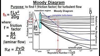
Moody Chart Application
Chapter 6 of 6
🔒 Unlock Audio Chapter
Sign up and enroll to access the full audio experience
Chapter Content
The Moody chart helps engineers determine friction factors based on Reynolds numbers and relative roughness, providing a practical tool for assessing energy losses in various pipe materials under real conditions.
Detailed Explanation
The Moody chart is a graphical representation that helps engineers find friction factors for different types of pipe flow conditions. By using the Reynolds number and roughness ratio, engineers can quickly assess how much energy will be lost in a system, making it a valuable tool in practical applications.
Examples & Analogies
Think of a menu at a restaurant where dishes are categorized by their popularity. Just as the menu helps you choose what to order based on previous customer experiences, the Moody chart allows engineers to choose the appropriate friction factor based on known flow conditions and pipe characteristics.
Key Concepts
-
Head Loss: The energy lost due to friction in fluid flow through pipes.
-
Friction Factor: Indicates resistance to flow and is used for calculating head loss.
-
Reynolds Number: Helps determine if fluid flow is laminar or turbulent.
-
Turbulent Flow: Causes higher energy losses due to chaotic fluid motion.
-
Pipe Roughness: Influences the energy dissipation rate in pipes.
Examples & Applications
Example of calculating head loss using the Darcy-Weisbach equation based on known pipe dimensions.
Comparing energy losses in a smooth pipe versus a roughened pipe to illustrate differences in flow resistance.
Memory Aids
Interactive tools to help you remember key concepts
Rhymes
In pipes so long, energy is lost, due to friction, it's a cost!
Stories
Imagine a crowded highway where cars (representing fluid) run into bumps (roughness) leading to slow speeds, much energy is lost in the delay!
Memory Tools
Friction Factors Effectively Relate (FFER) to flow conditions and pipe geometry.
Acronyms
HEAD = Head Loss Energy And Displacement (HEAD).
Flash Cards
Glossary
- Head Loss
The reduction in total head or energy of fluid flow through a pipe due to friction and turbulence.
- Friction Factor
A dimensionless number used to describe the frictional resistance to flow in a pipe.
- Reynolds Number
A dimensionless quantity that helps predict flow behavior in a pipe system.
- Turbulent Flow
A type of fluid flow characterized by chaotic changes in pressure and flow velocity.
- Roughness
The texture or irregularities of a pipe's internal surface that affects flow and energy loss.
Reference links
Supplementary resources to enhance your learning experience.