
Common Anode
Enroll to start learning
You’ve not yet enrolled in this course. Please enroll for free to listen to audio lessons, classroom podcasts and take practice test.
Interactive Audio Lesson
Listen to a student-teacher conversation explaining the topic in a relatable way.
Introduction to 7-Segment Displays
🔒 Unlock Audio Lesson
Sign up and enroll to listen to this audio lesson

Today, we'll learn about 7-segment displays, starting with a Common Anode configuration. Can anyone tell me what a Common Anode display is?

Is it a type of display where all the anodes are connected together?
Exactly! In a Common Anode display, all the anodes are connected to a positive voltage. Who can tell me how we might illuminate the individual segments here?

We would ground the individual cathodes to light them up!
That's correct! Remember, this is different from the Common Cathode configuration. Think of it as 'grounding to glow.'
Operational Mechanism
🔒 Unlock Audio Lesson
Sign up and enroll to listen to this audio lesson

Now let’s discuss the control mechanism. How do we manage a Common Anode display in a microcontroller environment?

Do we send low signals to the segments we want to turn on?
Right! By grounding the cathodes, we easily control which segments are illuminated. This makes logic control quite straightforward. Can anyone explain why this method is beneficial?

It simplifies the circuit design since we can use lower signals to activate segments!
Great point! This simplifies control and interfacing with a microcontroller significantly.
Applications of Common Anode Displays
🔒 Unlock Audio Lesson
Sign up and enroll to listen to this audio lesson
Lastly, let’s look at where Common Anode 7-segment displays are used. Who has an idea?
I've seen them in digital clocks!
And scoring displays too, like in games!
Absolutely! You’ll find them in clocks, counters, and various numerical readouts in electronics. Remember, they’re popular mainly because they’re straightforward to work with.
Introduction & Overview
Read summaries of the section's main ideas at different levels of detail.
Quick Overview
Standard
In a Common Anode 7-segment display, all anodes of the segment LEDs are connected to a positive voltage, and to illuminate a segment, the relevant cathode has to be grounded. This section explains the control mechanism, differences from Common Cathode displays, and practical applications.
Detailed
Common Anode 7-Segment Displays
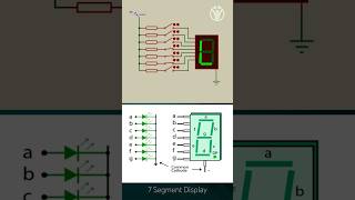
In this section, we delve into the workings of Common Anode 7-segment displays, a type of electronic display commonly used to represent numerical information in various devices. A Common Anode display connects all the anodes of its segments directly to the power supply. To illuminate any segment, the electronic circuit must pull the corresponding cathode down to ground level. This creates a clear distinction from Common Cathode displays, where the cathodes are connected to the power supply, necessitating a high signal to light the segments.
Key Concepts:
- Control Mechanism: The advantage of the Common Anode configuration is its ability to simplify interfacing with microcontrollers, as a low signal can turn segments on, allowing for direct logic control.
- Multiplexing: This configuration is especially beneficial in multiplexing applications, where multiple displays are controlled by a single set of GPIO pins, switching rapidly to give the appearance of simultaneous illumination.
- Applications: Common Anode displays are used in clocks, counters, and other devices needing numeric readouts, offering a balance between ease of use and functionality.
Understanding this configuration is vital for embedding control into display technology, especially in embedded systems where multiple displays or complex visuals are necessary.
Youtube Videos


Audio Book
Dive deep into the subject with an immersive audiobook experience.
Overview of Common Anode
Chapter 1 of 2
🔒 Unlock Audio Chapter
Sign up and enroll to access the full audio experience
Chapter Content
Common Anode: The anodes of all segments are connected together, and each segment is lit by grounding the corresponding cathode.
Detailed Explanation
In a common anode 7-segment display, all the positive connections (anodes) of the individual segments (LEDs) are connected together to a power supply. Instead of applying voltage to turn on a segment, we ground the negative terminal (cathode) of the segment we want to illuminate. This means we send a low signal to the specific segment's cathode while keeping all the anodes connected to the higher voltage. This method makes it straightforward to control which segments light up.
Examples & Analogies
Think of a common anode display like a row of switches connected to a battery. If all the switches (anodes) are connected to the battery, to turn on a specific light (LED segment), we need to flip the corresponding switch to the 'off' position, which connects it to the ground. Only then will the light illuminate, similar to how a streetlight turns on when connected to its ground wire.
Common Anode vs Common Cathode
Chapter 2 of 2
🔒 Unlock Audio Chapter
Sign up and enroll to access the full audio experience
Chapter Content
In contrast, a common cathode display has its cathodes connected together; segments are lit by applying a voltage to their anodes.
Detailed Explanation
In a common cathode 7-segment display, the negative sides (cathodes) of the LED segments are connected together and typically grounded. To turn on a segment, a positive voltage is applied to its anode. This configuration is the opposite of the common anode setup. Understanding the differences between these two types is crucial for designing circuits, as they dictate how you'll connect and control the display from a microcontroller.
Examples & Analogies
Imagine two types of outdoor lights: one set (common anode) requires you to pull down a switch at the base (ground) to turn them on, while the other set (common cathode) needs you to send power up to the switch (apply voltage). Knowing which setup you have will help you choose how to connect your wiring.
Key Concepts
-
Control Mechanism: The advantage of the Common Anode configuration is its ability to simplify interfacing with microcontrollers, as a low signal can turn segments on, allowing for direct logic control.
-
Multiplexing: This configuration is especially beneficial in multiplexing applications, where multiple displays are controlled by a single set of GPIO pins, switching rapidly to give the appearance of simultaneous illumination.
-
Applications: Common Anode displays are used in clocks, counters, and other devices needing numeric readouts, offering a balance between ease of use and functionality.
-
Understanding this configuration is vital for embedding control into display technology, especially in embedded systems where multiple displays or complex visuals are necessary.
Examples & Applications
A digital clock uses Common Anode displays to show time by lighting segments based on the time value.
Scoring counters in arcade games display scores using Common Anode configurations, simplifying electrical component layout.
Memory Aids
Interactive tools to help you remember key concepts
Rhymes
To make a segment glow, ground it, you know, Common Anode's the way to go!
Stories
Imagine a city where all the streetlights share a common power source. To turn on each light, you just flip the switch at the ground level, illuminating the night!
Memory Tools
A CAV: Common Anode Voltage - just Ground it to light up segments of a display!
Acronyms
G.A.N. - Ground All Neighbours to light up the Common Anode display!
Flash Cards
Glossary
- Common Anode
A configuration where the anodes of all segments in a 7-segment display are connected together to a positive voltage.
- Multiplexing
A technique used to control multiple displays with a single set of control signals by rapidly switching between the displays.
- GPIO
General Purpose Input/Output, a type of pin on a microcontroller that can be configured to function as either an input or output.
Reference links
Supplementary resources to enhance your learning experience.