
GPIO (General Purpose Input/Output) Peripherals
Enroll to start learning
You’ve not yet enrolled in this course. Please enroll for free to listen to audio lessons, classroom podcasts and take practice test.
Interactive Audio Lesson
Listen to a student-teacher conversation explaining the topic in a relatable way.
Understanding GPIO Basics
🔒 Unlock Audio Lesson
Sign up and enroll to listen to this audio lesson

Today, we'll dive into General Purpose Input/Output or GPIO. Who can tell me what GPIO pins are used for?

Are they used to connect the microcontroller to other devices?
Exactly! GPIO pins allow the microcontroller to interact with the external environment. We can configure them as inputs to read signals or outputs to control devices.

What kind of devices can we control with GPIO pins?
Great question! We can control LEDs, motors, and even read sensors. Remember, GPIO pins can be digital, meaning they can either be on or off. Can anyone think of a real-world example where GPIO might be used?

Maybe for reading a button press?
Exactly! Button inputs are a common application. Let's summarize: GPIO pins can be inputs for reading signals like button presses and outputs for controlling devices like LEDs.
GPIO Configuration Options
🔒 Unlock Audio Lesson
Sign up and enroll to listen to this audio lesson

Now that we know what GPIO pins are, let's talk about how we can configure them. What are the modes we can set GPIO pins to?

They can be set as input or output.
Correct! In input mode, they can read signals from external devices, while in output mode, they send signals. We also have to consider pull-up or pull-down resistors. Who can explain what these are?
They help keep the input signal stable when the pin is not actively driven?
Yes! Pull-up resistors pull the signal to a high state, while pull-down resistors pull it to low when the pin is not in use. This ensures we have consistent readings. Let’s recap: GPIO pins can be inputs to read external signals or outputs to control devices, complemented by pull-up or pull-down resistors for stability.
Interrupts and Events in GPIO
🔒 Unlock Audio Lesson
Sign up and enroll to listen to this audio lesson
Continuing with GPIO, let’s discuss interrupts. How can GPIO pins generate interrupts?
I think they can detect changes in the input signal, like when a button is pressed.
Correct! When the state of a GPIO pin changes, it can trigger an interrupt to the microcontroller, alerting it to respond quickly. Why might this be important?
It allows the system to react to events in real-time.
Exactly. This feature is especially useful in event-driven applications. Let’s summarize: GPIO pins can trigger interrupts based on signal changes, allowing immediate responses to events.
Applications of GPIO
🔒 Unlock Audio Lesson
Sign up and enroll to listen to this audio lesson
Now, let’s discuss applications of GPIO. What are some real-world uses for GPIO pins?
Controlling LEDs and reading button presses!
That's right! GPIOs are commonly used for reading inputs from buttons or switches and controlling outputs like LEDs or other devices. What else can we think of?
How about generating signals for testing?
Absolutely! GPIO can generate simple square waves for various signal processing tasks. Let’s recap: GPIO's applications include reading user inputs, controlling indicators like LEDs, and generating test signals.
Introduction & Overview
Read summaries of the section's main ideas at different levels of detail.
Quick Overview
Standard
This section discusses GPIO (General Purpose Input/Output) peripherals, detailing their configuration as inputs or outputs, the role of pull-up/pull-down resistors, and their applications in reading user inputs and controlling devices. Furthermore, it highlights the capability of GPIO pins to generate interrupts based on external signals, enhancing functionality in embedded systems.
Detailed
GPIO (General Purpose Input/Output) Peripherals
GPIO (General Purpose Input/Output) pins are versatile interfaces that allow microcontrollers to connect and communicate with external devices. These pins can be configured as either inputs or outputs, depending on the application's requirements. When set to input mode, GPIO pins can read signals from external components like switches or sensors; in output mode, they can control devices such as LEDs and motors. In addition, GPIO pins can employ internal pull-up or pull-down resistors to stabilize voltage levels when not actively driven, ensuring reliable signal readings.
One of the significant features of GPIO pins is their ability to generate interrupts. For example, a GPIO pin can trigger an interrupt when there’s a change in its input state, such as when a button is pressed. This is vital for event-driven applications, where immediate response to events (like user interactions) is necessary. The applications for GPIO are abundant, including reading button inputs, controlling LEDs, and generating simple signals for testing or processing purposes. Overall, understanding GPIO capabilities can significantly enhance the design and functionality of embedded systems.
Youtube Videos
Audio Book
Dive deep into the subject with an immersive audiobook experience.
GPIO Overview
Chapter 1 of 4
🔒 Unlock Audio Chapter
Sign up and enroll to access the full audio experience
Chapter Content
A GPIO pin can be configured as an input (to read external signals) or an output (to send signals to external devices).
Detailed Explanation
A GPIO pin serves as a point of interaction between the microcontroller and external devices. It can function as an input, which allows it to receive signals from other devices like switches or sensors, or as an output, which enables it to send signals to devices such as LEDs or motors.
Examples & Analogies
Think of a GPIO pin like a light switch. When you flip the switch on (output), you send power to a light bulb (external device). When you flip it off, you stop the flow of electricity. Similarly, when the switch is in the off position (input), it can sense whether the power is on or off, like detecting whether someone has flipped a different switch in another room.
GPIO Pin Configuration
Chapter 2 of 4
🔒 Unlock Audio Chapter
Sign up and enroll to access the full audio experience
Chapter Content
GPIO Pin Configuration:
- Input Mode: The pin reads signals from external devices, such as switches, sensors, or communication lines.
- Output Mode: The pin drives external devices like LEDs, motors, or relays.
- Pull-up/Pull-down Resistors: GPIO pins can be configured with internal pull-up or pull-down resistors to ensure stable voltage levels when the pin is not actively driven.
- Open-drain Output: Some GPIO pins can be configured as open-drain, allowing them to drive low or be left floating (for use in I2C communication or shared-bus scenarios).
Detailed Explanation
GPIO pins can be configured in various ways to perform their functions effectively:
1. Input Mode: Configured to read signals from devices, allowing the microcontroller to receive information.
2. Output Mode: Configured to send signals to devices, controlling their operation.
3. Pull-up/Pull-down Resistors: These resistors help maintain a stable signal (either HIGH or LOW) even when the pin is not being actively used, preventing it from floating, which can lead to unreliable behavior.
4. Open-drain Output: This configuration allows the pin to either pull the output to a low state or leave it floating, making it useful for wired communication protocols like I2C where multiple devices might share the same line.
Examples & Analogies
Imagine a light switch with an indicator LED. In Input Mode, the switch tells the microcontroller whether it is on or off. In Output Mode, the microcontroller can turn the LED on or off. The pull-up resistor ensures if the switch is open (off), the line recognizes this as off instead of potentially floating between on and off. An open-drain output is like a gate that can either slam shut (pulling low) or stay wide open (floating) without affecting other gates on a shared path.
Interrupts on GPIO
Chapter 3 of 4
🔒 Unlock Audio Chapter
Sign up and enroll to access the full audio experience
Chapter Content
GPIO pins can generate interrupts when there is a change in the input signal (e.g., when a button is pressed or a sensor state changes). This feature is often used in event-driven applications like external button presses or motion detection.
Detailed Explanation
When a GPIO pin is set to receive inputs, it can trigger an interrupt if it detects a change, such as when a button is pressed. This means that instead of constantly checking the state of the pin, the microcontroller can wait until it receives a notification (the interrupt), allowing it to respond quickly to changes. This capability is particularly advantageous in applications where the microcontroller needs to react to real-time events, such as detecting motion or user interactions.
Examples & Analogies
Consider a doorbell connected to a GPIO pin. Instead of the microcontroller constantly checking if the doorbell is pressed (which wastes energy), it can sit in idle mode until the bell rings. When the button is pressed, the doorbell sends an interrupt that signals the microcontroller to 'wake up' and perform an action, like playing a sound or lighting up an indicator.
Applications of GPIO
Chapter 4 of 4
🔒 Unlock Audio Chapter
Sign up and enroll to access the full audio experience
Chapter Content
Applications of GPIO:
- Button and Switch Inputs: Used for reading user input, such as pressing buttons or toggling switches.
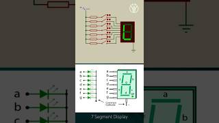
- LED Control: Used for turning LEDs on or off, as indicators or visual feedback devices.
- Signal Generation: GPIOs can generate simple square waves for signal processing or testing.
Detailed Explanation
GPIO pins have diverse applications in embedded systems:
1. Button and Switch Inputs: GPIOs are commonly used to detect user interactions, like when a button is pressed.
2. LED Control: GPIOs can directly control LEDs, displaying feedback by lighting them up in response to certain inputs.
3. Signal Generation: They can produce basic square wave signals, which are helpful in applications like generating clock signals for other components or simple sound signals for alerts.
Examples & Analogies
Imagine using GPIOs in a children's toy. When a child presses a button (the GPIO pin), the toy lights up (LED), showing that it's active. The toy can also create sound effects resembling a musical note, made by generating square wave signals with the GPIO. Each function uses the GPIO interface for different yet essential tasks.
Key Concepts
-
GPIO: Pins that allow interaction with external devices through digital signals.
-
Input Mode: Configuring a GPIO pin to read external signal states.
-
Output Mode: Configuring a GPIO pin to send signals to external devices.
-
Pull-up/Down Resistors: Stabilizing voltage levels for reliable GPIO signals.
-
Interrupts: Alerting the CPU to respond to changes in GPIO input signals.
Examples & Applications
A GPIO pin configured as an input is used to read the state of a button.
A GPIO pin configured as an output controls an LED, turning it on or off depending on the desired signal.
Memory Aids
Interactive tools to help you remember key concepts
Rhymes
With GPIO, we can read and write, control devices and get it right.
Stories
Imagine GPIO pins as busy communication workers who can either listen to inputs like buttons or shout out commands to lights.
Memory Tools
I-O-P: Input is for reading, Output is for sending, Pull-up keeps it steady.
Acronyms
GIPO
- General
- Input
- Pins
- Output.
Flash Cards
Glossary
- GPIO
General Purpose Input/Output, a type of pin on a microcontroller used for digital input and output operations.
- Input Mode
Configuration of a GPIO pin to read external signals.
- Output Mode
Configuration of a GPIO pin to send signals to external devices.
- Pullup Resistor
An internal resistor that connects a GPIO pin to a high voltage level to ensure stable readings.
- Pulldown Resistor
An internal resistor that connects a GPIO pin to ground to maintain a low voltage state when not driven.
- Interrupt
A signal that alerts the CPU to respond to an event, often triggered by changes in GPIO input.
- EventDriven Application
A software architecture approach that reacts to external interactions or events.
Reference links
Supplementary resources to enhance your learning experience.