
Timer and GPIO Interaction
Enroll to start learning
You’ve not yet enrolled in this course. Please enroll for free to listen to audio lessons, classroom podcasts and take practice test.
Interactive Audio Lesson
Listen to a student-teacher conversation explaining the topic in a relatable way.
Understanding Timers
🔒 Unlock Audio Lesson
Sign up and enroll to listen to this audio lesson

Welcome, class! Today we'll be diving into how timers work within embedded systems. Can anyone tell me what a timer does?

I think a timer counts up or down, right?
Exactly! Timers can measure time intervals by counting clock cycles. They can also generate interrupts when they reach a certain value. This helps in managing periodic tasks. There's a mnemonic to remember some types of timers: BPCM. Can anyone guess what it stands for?

Is it Basic, PWM, Capture, and Compare?
Spot on! Now, what are some applications of these timers?

Like controlling motors or generating audio signals.
Precisely! Timers are versatile in various applications. Let's move on to how they interact with GPIO.
GPIO Functionality
🔒 Unlock Audio Lesson
Sign up and enroll to listen to this audio lesson

Now, let’s explore GPIO. Who can explain what GPIO pins are used for?

They’re used to send and receive digital signals?
Correct! GPIO can be configured as inputs for reading signals or outputs for controlling devices. Remember the terms pull-up and pull-down resistors—who can explain these?
Pull-up resistors keep a pin high when not activated, and pull-down do the opposite!
Excellent! It’s crucial for ensuring stable voltage levels. How about we discuss how timers can influence GPIO?
Timer and GPIO Interactivity
🔒 Unlock Audio Lesson
Sign up and enroll to listen to this audio lesson
Let’s connect the dots. When a timer triggers an event, what can happen to a GPIO pin?
It can turn on or off an LED based on the timer's signals!
Exactly! This interaction enables complex behaviors in applications. Can someone give me a real-world example of this?
A digital clock uses a timer to increment seconds, and GPIO to update the display!
Great example! Such interactions are fundamental in real-time embedded systems.
Real-World Applications
🔒 Unlock Audio Lesson
Sign up and enroll to listen to this audio lesson
In our last session, let’s discuss real-world applications integrating timers and GPIO. Can anyone think of devices where this integration is critical?
Traffic lights use timers and GPIO to change signals at regular intervals.
Good thought! What other applications come to mind?
Home automation systems can schedule lights or appliances based on timers.
Exactly! This integration allows not just a response to user actions but also periodic automated tasks. Let’s summarize what we’ve learned.
We covered the role of timers, how GPIO pins function, and their interaction in various applications. This knowledge is vital for anyone working with embedded systems!
Introduction & Overview
Read summaries of the section's main ideas at different levels of detail.
Quick Overview
Standard
Timers and GPIO interact in embedded systems to enable control of external devices based on time-sensitive events. By generating periodic signals, timers can facilitate tasks such as LED control and event handling through GPIO, which illustrates essential concepts in embedded development.
Detailed
Timer and GPIO Interaction
In embedded systems, timers play a crucial role in generating periodic events, which can directly affect the operation of GPIO (General Purpose Input/Output) pins. This interaction allows microcontrollers to perform time-driven tasks efficiently, such as driving LEDs or monitoring switches.
Key Interactions:
- Periodic Events from Timers: Timers can generate interrupts or signals at regular intervals. These periodic events enable the CPU to perform specific tasks, such as checking the status of inputs.
- Control of GPIO Pins: GPIO pins can be configured to perform either input or output operations. A timer-driven event can change the state of a GPIO pin (e.g., turning an LED on or off), allowing for dynamic control based on time.
- Practical Applications: For instance, a timer can be set to trigger every second, at which point it checks the state of a GPIO input to see if a button has been pressed. If the button press is detected, the GPIO can then be programmed to activate an output device, such as an LED, for visual feedback.
Understanding the interaction between timers and GPIO is fundamental for designing effective embedded applications that require real-time response and device control.
Youtube Videos
Audio Book
Dive deep into the subject with an immersive audiobook experience.
Overview of Timer and GPIO Interaction
Chapter 1 of 4
🔒 Unlock Audio Chapter
Sign up and enroll to access the full audio experience
Chapter Content
Timers can be used to generate periodic events, which can trigger GPIO changes (e.g., controlling a relay or turning on an LED).
Detailed Explanation
This chunk explains how timers and GPIO (General Purpose Input/Output) interact within embedded systems. Timers are hardware components that can repeatedly count time or trigger events after set intervals. When a timer reaches a specified time, it can signal GPIO pins to carry out actions, such as turning on an LED or activating a relay. This interaction allows for controlled responses to timed events, facilitating automation and real-time operations in embedded systems.
Examples & Analogies
Consider setting a timer for a light to turn on automatically at dusk. The timer ticks away until it reaches the preset time, at which point it activates the GPIO connected to a relay. The relay then completes the circuit, turning the light on. This setup is similar to how timers and GPIOs work together in an embedded device.
GPIO Control Mechanisms
Chapter 2 of 4
🔒 Unlock Audio Chapter
Sign up and enroll to access the full audio experience
Chapter Content
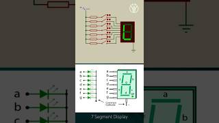
GPIO pins can be used to control a 7-segment display, either by directly driving the segments or by multiplexing multiple displays.
Detailed Explanation
In embedded systems, GPIO pins play a crucial role in driving output devices like 7-segment displays. There are two primary methods for controlling these displays using GPIO: direct connection and multiplexing. In direct control, each segment of the display is individually driven by a dedicated GPIO pin. In multiplexing, multiple displays share the same set of GPIO pins, with each display activated in quick succession to give the impression that all are lit at once. This efficiency in using fewer pins is vital in designs where resources are limited.
Examples & Analogies
Imagine you have several light bulbs in your house (the 7-segment displays), and you want to turn them on and off using a single switch (the GPIO). Using direct control, each bulb has its own switch to control it individually. However, if you use multiplexing, you control one bulb at a time so quickly that it appears all are on when viewed from afar, saving space and simplifying wiring.
Real-World Applications
Chapter 3 of 4
🔒 Unlock Audio Chapter
Sign up and enroll to access the full audio experience
Chapter Content
Real-World Applications: Digital Clocks: A timer generates clock pulses, and GPIO controls the 7-segment displays to show the current time.
Detailed Explanation
In practical applications, the interaction between timers and GPIO is evident in devices like digital clocks. In these clocks, a timer generates pulses that represent each second passing. The GPIO pins receive these signals and subsequently control the 7-segment displays to visually show the updated time. This concerted effort between the timer, which measures time, and the GPIO, which provides output, makes it possible for users to read the time easily.
Examples & Analogies
Think of a digital clock as a concert, where the timer acts as the conductor setting the tempo and the GPIO as the musicians who play the notes. The conductor (timer) sets the rhythm (time), and as each note (pulse) is played, the musicians (GPIO) light up different segments of the display, showing the correct time to the audience.
Event Counting and Display Functionality
Chapter 4 of 4
🔒 Unlock Audio Chapter
Sign up and enroll to access the full audio experience
Chapter Content
Event Counting and Display: GPIO pins are used to monitor external inputs (e.g., a button press or sensor event), and the timer keeps track of the time elapsed. The 7-segment display shows the result.
Detailed Explanation
Timers and GPIO interactions are critical for applications that involve event counting. In this scenario, GPIO pins monitor inputs such as button presses or notifications from sensors. Each event can trigger a change in the output displayed on a 7-segment display, showing how many times an event occurred. The timer helps keep track of the duration of these events, ensuring that the system can provide accurate feedback or perform both time-based and event-based operations effectively.
Examples & Analogies
Imagine a race track with buttons placed along the edge that a race timer counts. Each time a runner passes a checkpoint (button press), a GPIO pin detects the press and increments the count displayed on a scoreboard (7-segment display). Meanwhile, the race timer ensures the overall time taken is recorded simultaneously, allowing clear visibility of both the elapsed time and the number of laps completed.
Key Concepts
-
Periodic Events: Events triggered at regular intervals for time-sensitive tasks.
-
GPIO Pins: Configurable pins for digital input/output operations.
-
Timer Configuration: Setting up timers for specific intervals and triggering actions.
-
Event-Driven Control: Using GPIO to respond to timer-generated events.
Examples & Applications
A traffic light system where timers control the duration of light changes, and GPIO manages the light signals.
A digital clock where timers keep track of time, and GPIO updates the display based on the time count.
Memory Aids
Interactive tools to help you remember key concepts
Rhymes
Timers count and GPIO is neat, controlling devices is their main feat.
Stories
Imagine a digital clock at the wall, where a timer ticks and GPIO answers the call to display the time for one and all.
Memory Tools
To remember the function of GPIO, think: 'Go Put Inputs/Outputs' for your device.
Acronyms
GREAT for GPIO
General
Read/Output
Every
Action
Timer.
Flash Cards
Glossary
- Timer
A peripheral that counts clock cycles to generate events or measure time intervals.
- GPIO
General Purpose Input/Output pins used for digital signal I/O.
- Interrupt
A signal that prompts the CPU to stop its current activities and execute a specific task.
- Periodic Event
An event generated at regular intervals, often used in timers.
- Pullup Resistor
A resistor that connects an input pin to a high logic level when not active.
- Pulldown Resistor
A resistor connecting an input pin to a low logic level when not active.
Reference links
Supplementary resources to enhance your learning experience.