
GPIO and 7-Segment Displays
Enroll to start learning
You’ve not yet enrolled in this course. Please enroll for free to listen to audio lessons, classroom podcasts and take practice test.
Interactive Audio Lesson
Listen to a student-teacher conversation explaining the topic in a relatable way.
Introduction to GPIO
🔒 Unlock Audio Lesson
Sign up and enroll to listen to this audio lesson

Today, we will explore GPIO, which stands for General Purpose Input/Output. These pins allow microcontrollers to interact with the external world. Can anyone tell me what functions GPIO pins can perform?

They can read input signals from buttons and sensors!
Excellent! GPIO pins can indeed be configured to read inputs or send signals as outputs. When set as outputs, they can control devices like LEDs or motors. Memorable tips to remember GPIO functionality are: 'Input is In' and 'Output is Out'. Why is it important to have pull-up and pull-down resistors?

They help stabilize the voltage level when the pin is not driven active?
That's correct! These resistors ensure stable pin states, preventing erratic behavior. Let's move on to another key concept—what are the main applications for GPIO?

They can detect button presses and control LEDs!
Right again! GPIO is versatile and used for many applications in embedded systems to interact with the physical world. To summarize, GPIO pins can read inputs, drive outputs, and include configurations to ensure stability in signal states.
Understanding 7-Segment Displays
🔒 Unlock Audio Lesson
Sign up and enroll to listen to this audio lesson

Next, let's discuss 7-segment displays. These are essential for displaying numeric information visually. Who can tell me how a 7-segment display is structured?

They consist of seven LEDs arranged to form digits!
Exactly! Each segment can be lit in different combinations to represent numbers 0-9, as well as some letters and symbols. Can anyone explain the difference between common anode and common cathode displays?
In common anode, all anodes are connected, and to light a segment, you ground the cathode. For common cathode, vice versa, you apply voltage to the anode.
Great explanation! Also, multiplexing is crucial for controlling multiple displays effectively. Who can describe how we manage that?
We light one display at a time rapidly to make it seem like all are lit!
Yes! This method conserves resources and works well in embedded systems requiring visual output. Remember, digital encoding translates decimal values into specific segment controls. Summarizing, 7-segment displays can visually communicate numbers and characters, enhancing user interfaces.
Integrating GPIO with 7-Segment Displays
🔒 Unlock Audio Lesson
Sign up and enroll to listen to this audio lesson
Now, let’s integrate what we've learned. How can GPIO be used to control a 7-segment display?
We can connect GPIO pins directly to the segments!
Correct! By configuring the GPIO pins appropriately, we can send signals that control which segments light up. Can anyone think of a practical application of this integration?
Digital clocks! A timer can provide the pulse while GPIO controls the display.
Exactly! Such applications showcase the synergy between timers, GPIO, and displays to create functioning systems. Please remember, this integration allows for dynamic visual representation, bridging the microcontroller with user interfaces. In summary, GPIO and 7-segment displays work together to provide effective feedback and control in embedded systems.
Introduction & Overview
Read summaries of the section's main ideas at different levels of detail.
Quick Overview
Standard
GPIO (General Purpose Input/Output) acts as a bridge for microcontrollers to interface with various devices, while 7-segment displays provide a means to visually present numeric data. This section explores how these components work together to enhance embedded system applications.
Detailed
GPIO and 7-Segment Displays
In embedded systems, GPIO (General Purpose Input/Output) and 7-segment displays serve important roles in interfacing and visual output.
GPIO Overview
GPIO pins are versatile interfaces that can be configured as either inputs or outputs. When set as inputs, they read signals from buttons and sensors, whereas as outputs, they control devices such as LEDs and motors. Key configurations include pull-up and pull-down resistors, which stabilize pin states when inactive, and open-drain outputs that facilitate shared-bus communications.
Interrupt Handling
GPIO pins can also generate interrupts, which allow microcontrollers to respond promptly to changes in input signals, making them suitable for event-driven applications such as button presses or sensor activations.
Applications of GPIO
- Button and Switch Inputs: Utilized for user inputs.
- LED Control: Enabling visual feedback through LED illumination.
- Signal Generation: Producing square wave outputs for various applications.
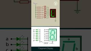
7-Segment Display Overview
A 7-segment display comprises seven LEDs that can illuminate to represent numeric values. The displays can be classified into common cathode and common anode types, each differing in electrical configuration.
Display Control
Multiplexing is a common technique used to manage multiple 7-segment displays, wherein each display is activated in quick succession, creating the illusion that all displays are simultaneously active.
Encoding and Applications
To control the display, decimal values are encoded into 7-bit signals corresponding to the segments needed to form specific digits. The versatility of 7-segment displays allows their application in clocks, counters, and various simple digital readouts, effectively providing real-time visual information.
Youtube Videos
Audio Book
Dive deep into the subject with an immersive audiobook experience.
Interactions Between GPIO and 7-Segment Displays
Chapter 1 of 3
🔒 Unlock Audio Chapter
Sign up and enroll to access the full audio experience
Chapter Content
GPIO pins can be used to control a 7-segment display, either by directly driving the segments or by multiplexing multiple displays.
Detailed Explanation
In embedded systems, GPIO pins act as the interface for microcontrollers to communicate with external devices. When controlling a 7-segment display, GPIO pins can either be connected directly to the individual segments of the display, turning them on and off to form numbers and characters. Alternatively, if there are multiple displays, we can use a technique called multiplexing. Multiplexing involves controlling multiple displays by switching between them rapidly, creating the illusion that all displays are active at the same time.
Examples & Analogies
Imagine a stage with several performers (the 7-segment displays), but only one performer can be illuminated at a time (the one that the GPIO controls). By quickly changing the spotlight (the GPIO signal) from one performer to another, the audience perceives that all performers are dancing simultaneously, just like multiple displays appearing to show numbers at once.
Real-World Applications of GPIO and 7-Segment Displays
Chapter 2 of 3
🔒 Unlock Audio Chapter
Sign up and enroll to access the full audio experience
Chapter Content
Real-World Applications: Digital Clocks: A timer generates clock pulses, and GPIO controls the 7-segment displays to show the current time.
Detailed Explanation
One common application of integrating GPIO and 7-segment displays is in digital clocks. In this setup, a timer generates clock pulses at regular intervals, which serve as a clock signal or timekeeper. These pulses activate the GPIO pins that control the 7-segment displays, translating the time information into visual numeric displays. For example, every minute, the timer sends a pulse; the GPIO logic converts this pulse into the corresponding numerical representation on the display, effectively updating the time shown.
Examples & Analogies
Think of a digital clock as a dance performance where the timer is the conductor, issuing signals to the dancers (the segments of the display). When the conductor raises their baton (the timer pulse), the dancers (segments) know it's time to step forward and light up, forming the current time for the audience (the viewers of the clock).
Event Counting and Display Integration
Chapter 3 of 3
🔒 Unlock Audio Chapter
Sign up and enroll to access the full audio experience
Chapter Content
Event Counting and Display: GPIO pins are used to monitor external inputs (e.g., a button press or sensor event), and the timer keeps track of the time elapsed. The 7-segment display shows the result.
Detailed Explanation
Another application involves using GPIO pins to track events, such as counting button presses or monitoring sensor activations. When an event occurs, such as a button being pressed, a GPIO pin registers the signal change and can trigger a timer to count how long it takes for a specific action to occur from that event. The accumulated count or elapsed time can be displayed on a 7-segment display, providing a visual representation of the data to the user.
Examples & Analogies
Consider a scoreboard at a game. Every time a player presses a button (the GPIO input), it adds a point (the timer counting), and the score is displayed on a large board (the 7-segment display). Just like in sports, where every point matters, in embedded systems, counting events accurately and displaying them clearly is crucial for monitoring performance.
Key Concepts
-
GPIO: Versatile pins used for reading inputs and driving outputs in microcontrollers.
-
7-Segment Display: An arrangement of LEDs used to display numeric digits.
-
Multiplexing: Technique used to control multiple displays effectively by rapidly switching between them.
-
Common Anode vs Common Cathode: Distinction in 7-segment display connections influencing how segments are lit.
Examples & Applications
A digital clock where GPIO controls the segments of the 7-segment display to show the current time.
A scoreboard using multiple 7-segment displays to showcase scores, driven by GPIO pins.
Memory Aids
Interactive tools to help you remember key concepts
Rhymes
LEDs glow as numbers show, segments light up in a row!
Stories
Imagine a busy digital clock, with hands racing to display the time. Each segment represents a number, working together in harmony like a well-rehearsed team, illuminating bright as seconds tick away.
Memory Tools
For GPIO, think 'In and Out' to remember input-output roles.
Acronyms
G-I-P for GPIO stands for General Input Output, a simple way to recall!
Flash Cards
Glossary
- GPIO
General Purpose Input/Output; pins on a microcontroller that can serve as either input or output interfaces.
- 7Segment Display
A display device made of seven LED segments that can be illuminated in various combinations to show numbers.
- Multiplexing
A technique to control multiple displays by activating them in quick succession.
- Common Anode
A configuration in a 7-segment display where all anodes are connected together.
- Common Cathode
A configuration where all cathodes are connected together, and segments are lit by applying voltage to their anodes.
- Pullup/Pulldown Resistors
Resistors used in GPIO configurations to maintain stable voltage levels when no active signal is present.
Reference links
Supplementary resources to enhance your learning experience.