
Timer, GPIO, and 7-Segment Peripherals
Enroll to start learning
You’ve not yet enrolled in this course. Please enroll for free to listen to audio lessons, classroom podcasts and take practice test.
Interactive Audio Lesson
Listen to a student-teacher conversation explaining the topic in a relatable way.
Introduction to Peripherals
🔒 Unlock Audio Lesson
Sign up and enroll to listen to this audio lesson

Good morning class! Today we're delving into peripherals, crucial components allowing microcontrollers to interact with the outside world. Can anyone explain why peripherals are necessary?

They help the microcontroller communicate with sensors and other devices, right?
Exactly! They expand the microcontroller's functionality. We’ll particularly focus on timers, GPIO, and 7-segment displays today.

What does AHB mean in this context?
Good question! AHB stands for Advanced High-performance Bus, facilitating efficient communication between the processor and these peripherals. Remember, AHB = Accelerated High-speed Bridges!

So, without these peripherals, the microcontroller couldn’t interact with the environment?
Correct! They enable the necessary interactions in various applications, from alarms to data logging.
Timer Peripherals
🔒 Unlock Audio Lesson
Sign up and enroll to listen to this audio lesson

Next, let's explore timers! Can anyone tell me what a basic timer does?
It counts clock cycles and triggers events, right?
Exactly! Basic timers generate interrupts after counting to a preset value. What about PWM timers? Anyone knows what they do?
They generate variable-width pulses for controlling motors, like in motor control applications!
Well said! PWM = Pulse Width Modulation, remember it to associate with motor control. Now, what applications can we think of for timers?
Real-time clocks and measuring external events?
Exactly! Timers are indeed vital for such tasks. Let's summarize: Timers help keep track of time and manage events in embedded systems.
GPIO Peripherals
🔒 Unlock Audio Lesson
Sign up and enroll to listen to this audio lesson
Now, let's dive into GPIO! Who can describe what GPIO pins do?

They allow the microcontroller to read inputs or send outputs!
Correct! Remember, GPIO = General Purpose Input/Output. Why is this versatility important?
It allows the microcontroller to interface with multiple devices, like switches and LEDs.
Absolutely right! Can someone explain how pull-up or pull-down resistors work?
They stabilize pin voltage levels when not driven by external sources!
Perfect! This capability is crucial for detecting stable input states. Finally, how do we control an LED with GPIO?
By configuring the pin as output and sending a high signal!
Great job! LEDs and GPIO work hand in hand.
7-Segment Displays
🔒 Unlock Audio Lesson
Sign up and enroll to listen to this audio lesson
Now let's explore 7-segment displays! Can anyone tell me how they work?
Each segment lights up to represent numbers, right?
Exactly! They use combinations of 7 LEDs. Why might we use 7-segment displays in our projects?
To show numeric values, like in clocks or scoreboards!
Well done! Now, how is multiplexing relevant for displaying multiple digits?
We can switch between displays rapidly so it looks like all are lit at the same time!
Exactly! Multiplexing optimizes resource use. Let’s summarize: 7-segment displays efficiently show numerical data through clever LED configurations.
Integration of Timers and GPIO with 7-Segment Displays
🔒 Unlock Audio Lesson
Sign up and enroll to listen to this audio lesson
To wrap up, let's discuss how we've integrated timers, GPIO, and 7-segment displays. How do you think a digital clock would use these peripherals?
The timer generates clock pulses, and GPIO controls the 7-segment display for the time!
Spot on! What about counting events using GPIO and displaying them?
GPIO captures the events, and we display the count using the 7-segment display!
Exactly! Integration is key in embedded systems for enhanced functionality. What are essential performance considerations with these peripherals?
We need to think about latency, power consumption, and data throughput!
Perfect summarization! Keep these factors in mind when designing systems.
Introduction & Overview
Read summaries of the section's main ideas at different levels of detail.
Quick Overview
Standard
The section emphasizes the integration and operation of timers for timing tasks, GPIO for input/output operations, and 7-segment displays for numeric displays, outlining their applications and significance in embedded system environments.
Detailed
Timer, GPIO, and 7-Segment Peripherals
This section provides a comprehensive examination of three vital peripherals in embedded systems: Timers, GPIO (General Purpose Input/Output), and 7-segment displays. Each plays a crucial role in enhancing microcontroller functionality and user interaction.
8.1 Introduction to Peripherals
Peripherals extend microcontroller capabilities by facilitating interaction with the external environment, significantly enhancing the system's functionality. In this section, we outline how peripherals link to the microcontroller via the AHB (Advanced High-performance Bus), allowing efficient communication and control.
8.2 Timer Peripherals
Timers are indispensable for executing precise timing tasks and event counting. Here, we distinguish between several types of timers—Basic, PWM, and Capture/Compare timers—each serving unique applications. Key components of timers include prescalers and counters, which help enable events and interrupts for task management.
8.3 GPIO Peripherals
GPIO pins serve as interfaces for microcontrollers to communicate with external devices. They can be configured for binary input or output and incorporate features like pull-up/down resistors and interrupt capabilities. Applications include reading switches and controlling LEDs.
8.4 7-Segment Display Peripherals
7-segment displays visualize numerical data by illuminating specific segments. Understanding control mechanisms like multiplexing and digital encoding is emphasized, while the applications of 7-segment displays in clocks and counters are also discussed.
8.5 AHB Interface
The integration of these peripherals through memory-mapped I/O and the AHB bus facilitates seamless communication and interrupts, ensuring high-efficient data transfer and control.
8.6 Integration and Applications
The section highlights how these components interrelate in real-world systems, for instance in digital clocks, showcasing their combined effectiveness and utility.
8.7 Performance Considerations
Performance aspects such as latency, data throughput, and power consumption are critical in designing efficient systems that optimize the use of these peripherals.
By grasping the significant roles and configurations of these peripherals, engineers can craft optimized solutions for a multitude of applications.
Youtube Videos
Audio Book
Dive deep into the subject with an immersive audiobook experience.
Introduction to Peripherals
Chapter 1 of 11
🔒 Unlock Audio Chapter
Sign up and enroll to access the full audio experience
Chapter Content
Peripherals are components that allow the processor to interact with the external environment, such as input devices, output devices, or communication interfaces. This chapter covers three common types of peripherals in embedded systems: Timers, GPIO (General Purpose Input/Output), and 7-Segment Displays.
● Purpose of Peripherals: Peripherals expand the functionality of a microcontroller, enabling it to handle time-sensitive tasks, interact with external devices, and display data to users.
● Integration with the AHB: These peripherals often interface with the microcontroller’s AHB (Advanced High-performance Bus), enabling efficient communication and control.
Detailed Explanation
In embedded systems, peripherals serve as the bridge between the microcontroller and the outside world. They include devices that allow us to interact with things like buttons, lights, and other sensors. For instance, a timer can help in keeping track of time, GPIO pins can read inputs from switches, and 7-segment displays can show numbers. These peripherals essentially augment what the microcontroller can do, allowing for a richer feature set. Additionally, peripherals typically connect to the microcontroller through a system called the AHB, which facilitates fast communication.
Examples & Analogies
Imagine a smartphone that helps you manage your daily life. The processor is like the brain of the phone, while the peripherals (like the camera for photos, GPS for navigation, or touchscreen interface for interactions) are like the senses that help the phone understand and react to its environment.
Timer Overview
Chapter 2 of 11
🔒 Unlock Audio Chapter
Sign up and enroll to access the full audio experience
Chapter Content
Timers are essential for generating precise delays, time measurements, and event counting in embedded systems. They are used in applications like real-time clocks, event timing, and pulse generation.
● Timer Overview: A timer generates periodic interrupts or generates events after a specific duration. Timers in microcontrollers are typically implemented using a counter that increments on each clock cycle.
Detailed Explanation
Timers play a critical role in embedded systems by ensuring that time-sensitive operations can be performed. They work by counting clock cycles, which are all the ticks made by the microcontroller's clock. For example, if you need to wait for one second before turning on an LED, a timer can be set to count until it reaches the number of ticks that corresponds to one second and then trigger an action when that limit is reached. This allows for actions that must happen at specific times.
Examples & Analogies
Think of a timer like a stopwatch during a race. The stopwatch counts the seconds and alerts the runner when a certain time is reached—just like a timer in a microcontroller counts clock ticks and lets it know when to perform a task.
Types of Timers
Chapter 3 of 11
🔒 Unlock Audio Chapter
Sign up and enroll to access the full audio experience
Chapter Content
● Types of Timers:
○ Basic Timers: Simple timers that count clock cycles and trigger an interrupt or event after reaching a preset value.
○ PWM (Pulse Width Modulation) Timers: Timers that generate variable-width pulses for applications such as motor control, audio generation, and signal modulation.
○ Capture/Compare Timers: Timers that can capture the time when an event occurs (capture mode) or compare the counter value with a predefined value and trigger an action (compare mode).
Detailed Explanation
There are different types of timers, each serving specific functions in an embedded system. Basic timers simply count until a defined limit is reached. PWM timers are more complex, allowing variable signals—these are used in things like controlling motor speed where you need to adjust how fast a motor runs. Capture/compare timers serve a dual function, being able to record time when events happen and comparing times for actions like turning on a light at the right moment.
Examples & Analogies
If you think of timers in a kitchen, a basic timer is like a microwave timer that just counts down until it stops. A PWM timer is like a dimmer switch that can adjust the brightness of a lightbulb (not just on or off), while a capture timer is similar to a stopwatch that not only tells you how long something has been cooking but can also remind you when to check it again at a specific time.
Applications of Timers
Chapter 4 of 11
🔒 Unlock Audio Chapter
Sign up and enroll to access the full audio experience
Chapter Content
● Applications of Timers:
○ Real-Time Clock (RTC): Used to keep track of real-world time, typically in embedded systems like alarm clocks or data logging systems.
○ Event Counting: Counting external events or pulses from sensors (e.g., measuring frequency).
○ Time Delay Generation: Creating precise delays for operations, often in communication protocols or motor control.
Detailed Explanation
Timers have important applications in embedded systems. For example, Real-Time Clocks (RTC) keep accurate time, which is crucial in devices like alarm clocks. Additionally, timers can count events, such as how many times a button is pressed, which is helpful in applications like frequency measurement. Lastly, timers can create delays to ensure that tasks happen in a specific sequence, which is particularly vital in communication systems where timing can affect signals.
Examples & Analogies
Consider a digital wristwatch. It uses a timer to track and display the current time, just like an alarm clock does. When you press the button to start a stopwatch for your workout, it's counting how many seconds you've been running, and if you need to pause before switching tasks, a timer creates a delay before the next notification shows up.
GPIO Overview
Chapter 5 of 11
🔒 Unlock Audio Chapter
Sign up and enroll to access the full audio experience
Chapter Content
GPIO (General Purpose Input/Output) pins provide an interface for a microcontroller to interact with the external world. They are used for simple digital input and output operations, allowing the processor to control or read from various external devices.
Detailed Explanation
GPIO pins are versatile components that enable microcontrollers to interact with other circuits. These pins can be configured either to receive data (input) from external devices, like buttons or sensors, or to send data (output) to components such as LEDs or motors. This flexibility allows for straightforward interactions between a microcontroller and the components it controls or monitors.
Examples & Analogies
Think of GPIO pins like the windows and doors of a house. Just as you can open a window to let fresh air in (input) or close it to keep the window shut (output), GPIO pins can either receive signals from outside (like senses) or send signals out to control devices like lights and alarms.
GPIO Pin Configuration
Chapter 6 of 11
🔒 Unlock Audio Chapter
Sign up and enroll to access the full audio experience
Chapter Content
● GPIO Pin Configuration:
○ Input Mode: The pin reads signals from external devices, such as switches, sensors, or communication lines.
○ Output Mode: The pin drives external devices like LEDs, motors, or relays.
○ Pull-up/Pull-down Resistors: GPIO pins can be configured with internal pull-up or pull-down resistors to ensure stable voltage levels when the pin is not actively driven.
Detailed Explanation
GPIO pins can be set to different modes depending on their role. In input mode, they can read whether a button is pressed or if a sensor detects something. When in output mode, they can turn on an LED or activate a relay. The configuration can also include pull-up or pull-down resistors, which help maintain a stable signal when a pin is not actively sending a signal, preventing false readings.
Examples & Analogies
Imagine a light switch powered by a battery. If the switch (analogous to a GPIO pin) is open (input mode), it can tell you whether the circuit is complete (perhaps by using a light sensor). When you turn it on (output mode), it lights up the bulb. The pull-up/pull-down resistor is like a line of support that keeps the circuit steady until you're ready to flip the switch.
Interrupts on GPIO
Chapter 7 of 11
🔒 Unlock Audio Chapter
Sign up and enroll to access the full audio experience
Chapter Content
● Interrupts on GPIO: GPIO pins can generate interrupts when there is a change in the input signal (e.g., when a button is pressed or a sensor state changes). This feature is often used in event-driven applications like external button presses or motion detection.
Detailed Explanation
GPIO pins can generate interrupts, which are notifications sent to the microcontroller when a change occurs, like pressing a button. This is particularly useful in event-driven applications where immediate action may be required. For instance, if a motion sensor detects movement, it can trigger an interrupt that tells the microcontroller to respond instantly, rather than continuously checking the state of the GPIO pin.
Examples & Analogies
Imagine a doorbell that rings when pressed. The button (the GPIO pin) sends an alert (an interrupt) to your house’s chime to ring instead of you having to keep checking when someone is at the door. This immediate response is how interrupts help the microcontroller efficiently focus on other tasks instead of checking continuously for input.
Applications of GPIO
Chapter 8 of 11
🔒 Unlock Audio Chapter
Sign up and enroll to access the full audio experience
Chapter Content
● Applications of GPIO:
○ Button and Switch Inputs: Used for reading user input, such as pressing buttons or toggling switches.
○ LED Control: Used for turning LEDs on or off, as indicators or visual feedback devices.
○ Signal Generation: GPIOs can generate simple square waves for signal processing or testing.
Detailed Explanation
GPIOs play a crucial role in applications where user interaction or visual feedback is needed. They can read inputs from buttons or switches, allowing user commands to be processed. GPIOs can also control LEDs to provide visual feedback, such as indicating if a system is on or off. Additionally, GPIOs can be programmed to generate signals, for instance, square waves used in testing other electronic components or systems.
Examples & Analogies
Consider a game controller where pressing buttons gives you feedback through lights turning on or off. Each button press is like a GPIO reading input, while the LEDs indicate what action is being performed. Similarly, when testing audio equipment, the GPIO might generate a beep or a tone to confirm everything is working, just like making sure the lights respond when you press a switch.
7-Segment Display Overview
Chapter 9 of 11
🔒 Unlock Audio Chapter
Sign up and enroll to access the full audio experience
Chapter Content
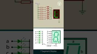
● 7-Segment Display Overview: Each of the seven segments in a display can be lit up individually to form the numbers 0-9. Additional characters can be displayed by lighting combinations of the segments.
Detailed Explanation
A 7-segment display is a common way to visually represent numbers in digital form. The display contains seven individual segments, each of which can be turned on or off to create the desired digit. By lighting up different combinations of these segments, various numbers from 0 to 9 can be shown, allowing for clear numerical representation in devices like clocks or scoreboards.
Examples & Analogies
Think of a digital scoreboard at a sports game that displays the score. Each number is made up of different segments lighting up, similar to how a set of seven light bars can act together to create a number. Just like you’d see segments turning on and off to form a 1 or a 7 on the scoreboard.
7-Segment Display Control
Chapter 10 of 11
🔒 Unlock Audio Chapter
Sign up and enroll to access the full audio experience
Chapter Content
● 7-Segment Display Control:
○ Multiplexing: In systems with multiple 7-segment displays, multiplexing is used to drive each display in turn. Only one display is illuminated at a time, but rapid switching between displays gives the illusion that all displays are showing numbers simultaneously.
○ Digital Encoding: To drive a 7-segment display, a binary or BCD (binary-coded decimal) value is encoded into a 7-bit control signal that corresponds to the required segments. This encoding ensures the correct number or character is displayed.
Detailed Explanation
When using multiple 7-segment displays, multiplexing is a technique that controls each display by illuminating one at a time very quickly, giving the impression that they are all lit simultaneously. This is effective in saving resources since only one display needs to be active at any time. Furthermore, to indicate a number on the display, a binary code (like a 7-bit pattern) is used to signal which segments should light up, ensuring the right number shows correctly.
Examples & Analogies
Imagine a concert where several spotlights are directed at different performers, but only one spotlight is on at a time. By switching between them quickly, the audience perceives that all performers are illuminated. Similarly, multiplexing allows each 7-segment display to light up in quick succession, while digital encoding ensures the correct number, like a performer taking the stage, shows on each display.
Applications of 7-Segment Displays
Chapter 11 of 11
🔒 Unlock Audio Chapter
Sign up and enroll to access the full audio experience
Chapter Content
● Applications of 7-Segment Displays:
○ Clocks: Displaying time in digital clocks or countdown timers.
○ Counters: Displaying numerical values, such as in scoreboards or counters.
○ Simple Readouts: Used in calculators, devices displaying measurements (e.g., temperature or voltage), and other simple digital readouts.
Detailed Explanation
7-segment displays are widely used in various applications that require numerical representation. Digital clocks use them to display time, and scoreboards employ them to show scores. They are also very common in calculators and devices that need to present measurements like temperatures or voltages in a straightforward manner, thanks to their clear and readable format.
Examples & Analogies
Think of a digital clock sitting on your bedside table. It uses a 7-segment display to show you the current time in a clear and organized manner. Similarly, the scoreboard at a basketball game uses these displays to keep track of the score, and your home thermometer might use a 7-segment display to show the current temperature outside.
Key Concepts
-
Timers: Essential for managing precise timing tasks in embedded systems.
-
GPIO: Provides a versatile interface for interacting with various external devices.
-
7-Segment Displays: Used to visually represent numeric data effectively.
-
AHB Interface: Enhances communication efficiency between the processor and peripherals.
-
Multiplexing: Allows multiple displays without requiring excessive I/O pins.
Examples & Applications
A digital clock using a timer to generate clock pulses and GPIO to display time on a 7-segment display.
Using GPIO to control LEDs based on sensor input to indicate system status.
Memory Aids
Interactive tools to help you remember key concepts
Rhymes
Timers tick with precise beats, measuring time in data seats.
Stories
In a land of circuits, a clock needed control. A timer ticked away, guiding LEDs to glow, showing time's flow for all to know. Thus, GPIO took charge, making lights dance with a spark!
Memory Tools
Remember 'T.G.S' for functions of timers, GPIO, and 7-segment displays: Timing, General Input/output, and Simple displays.
Acronyms
P.L.A.N. = PWM, Latency, AHB, Number displays to remember core concepts.
Flash Cards
Glossary
- Peripheral
A component that allows a microcontroller to interact with the external environment.
- Timer
A device that generates precise timing signals and events.
- GPIO
General Purpose Input/Output pins used for interfacing various devices.
- 7Segment Display
A display composed of 7 LEDs arranged to show numeric values.
- PWM
Pulse Width Modulation, a technique for varying the width of pulses in a signal.
- Multiplexing
A method to control multiple outputs by switching them rapidly.
- Pullup/Pulldown Resistors
Resistors used to ensure stable voltage levels for GPIO pins when not driven.
- Latency
The time delay between an input or event and the system’s response.
- Data Throughput
The rate at which data is transferred or processed in a system.
- MemoryMapped I/O
A method where peripherals are addressed in the same way as regular memory.
Reference links
Supplementary resources to enhance your learning experience.