
Common Cathode
Enroll to start learning
You’ve not yet enrolled in this course. Please enroll for free to listen to audio lessons, classroom podcasts and take practice test.
Interactive Audio Lesson
Listen to a student-teacher conversation explaining the topic in a relatable way.
Overview of Common Cathode Displays
🔒 Unlock Audio Lesson
Sign up and enroll to listen to this audio lesson

Today we're going to learn about Common Cathode 7-Segment Displays. Can anyone explain what is meant by a 'common cathode' display?

I think it means that the negative side of all the segments is connected together.
Exactly! The cathodes of the LEDs are joined and grounded, meaning the anodes must be activated to light up the segments. This makes it easier to control when displaying numbers. Can anyone tell me an application where we might use one?

Digital clocks! They always show numbers.
Good example! So, when we want to display '5', we would connect the anode of the segments that form '5' to a voltage source. Let's remember: Common Cathode means we control by applying voltages to the anodes.
The Multiplexing Method
🔒 Unlock Audio Lesson
Sign up and enroll to listen to this audio lesson

Now, let's discuss multiplexing. Can anyone tell me what multiplexing means in the context of displays?

Is it turning on multiple displays one at a time quickly to make it look like they're all on?
Correct! Multiplexing allows us to drive multiple displays by lighting them one at a time in quick succession. This reduces the number of pins needed on a microcontroller. So, if we have four displays, we only need to control the segments and select which display to activate in sequence. Remember to use this technique for efficiency!
Control Signals for Segment Display
🔒 Unlock Audio Lesson
Sign up and enroll to listen to this audio lesson
When controlling segment displays, we need specific control signals. What format does this information often take?

I think binary or something like BCD?
Right on target! We often use Binary-Coded Decimal (BCD) to represent the digits 0-9, which directly maps to the segments of the display. To represent the number '3', we can look at a binary number that activates the respective segments. Keep in mind this encoding is essential for proper display functionality.
Comparison with Common Anode
🔒 Unlock Audio Lesson
Sign up and enroll to listen to this audio lesson
Let's highlight the differences between common cathode and common anode displays. Who knows the main difference?
Common anode means all anodes are connected, right? And segments light when the cathodes are grounded?
Exactly! In a common anode display, you'd ground the segments to light them. The choice between the two usually depends on the application and the circuit design. Remembering these differences will help in selecting the right display for your projects.
Introduction & Overview
Read summaries of the section's main ideas at different levels of detail.
Quick Overview
Standard
Common cathode 7-segment displays connect all cathodes to ground, allowing an individual segment to illuminate when a voltage is applied to its anode. This configuration is crucial for displaying numerical data in various applications, and understanding its operation is key to effective peripheral management in microcontroller systems.
Detailed
In a common cathode 7-segment display, all the cathodes of the individual LED segments are connected together and grounded. To light up a specific segment, a voltage must be applied to its corresponding anode. This setup is particularly user-friendly, as it requires less complex circuitry compared to its counterpart, the common anode display, which requires grounding of segments to turn them on. Such displays are widely used in digital clock applications, counters, and simple readouts for devices. The exact configuration also allows efficient multiplexing when multiple displays are used, thus optimizing the overall system design and power consumption.
Youtube Videos


Audio Book
Dive deep into the subject with an immersive audiobook experience.
Overview of Common Cathode Displays
Chapter 1 of 3
🔒 Unlock Audio Chapter
Sign up and enroll to access the full audio experience
Chapter Content
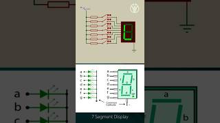
Common Cathode: The cathodes of all segments are connected together, and each segment is lit by applying a voltage to the corresponding anode.
Detailed Explanation
A common cathode 7-segment display has each of its segments' cathodes wired together. When you want to turn on a segment of the display, you apply a positive voltage (or logic high) to that segment's anode. The common connection to the cathode essentially completes the circuit, allowing current to flow through the segment, illuminating it. This means that in order to light up any segment, the cathode is always at a low voltage, and segments are turned on by sending a high signal to their respective anodes.
Examples & Analogies
Think of a common cathode display like a group of light bulbs connected to a battery. The battery represents the common ground (cathode) which connects to all bulbs. To turn a bulb on (light up a segment), you simply connect a wire to the battery and apply voltage to that wire, completing the circuit and allowing electricity to flow through the specific bulb.
Difference from Common Anode Displays
Chapter 2 of 3
🔒 Unlock Audio Chapter
Sign up and enroll to access the full audio experience
Chapter Content
Common Anode: The anodes of all segments are connected together, and each segment is lit by grounding the corresponding cathode.
Detailed Explanation
In a common anode display, the anodes of the segments are connected to a positive voltage. To light up a segment, you ground its cathode. This is the opposite of a common cathode display. For example, if the common anode is at 5V, you need to pull down the cathode to 0V to complete the circuit. This distinction is crucial because it affects how you control the display using microcontrollers and how you design your circuit.
Examples & Analogies
Imagine you're controlling water flow in a system where all pipes (anodes) are connected to a high tank (representing a positive supply). To release water from a specific pipe (lighting a segment), you would need to open a valve to drain the water level (grounding the cathode) from that particular pipe, allowing water to flow out.
Applications of Common Cathode Displays
Chapter 3 of 3
🔒 Unlock Audio Chapter
Sign up and enroll to access the full audio experience
Chapter Content
Common cathode displays are widely used in numerical displays such as clocks, counters, and devices displaying measurements.
Detailed Explanation
Common cathode displays are popular in a variety of applications due to their simplicity in control and wiring. They are typically used in devices that require straightforward numerical output, like digital clocks that show time or counters that track values. In these applications, the control signals can be easily managed through simple logic circuits or microcontroller outputs, enabling efficient operation.
Examples & Analogies
Consider a digital timer in a kitchen. It uses a common cathode display to show the countdown. Each time you press the button to set the timer, the segments light up to display the remaining time. Like a digital clock, it's easy to read and adjust, making it very practical in everyday life.
Key Concepts
-
Common Cathode: Understanding the basic connectivity of segments in the display.
-
Multiplexing: The technique of controlling multiple displays through rapid switching.
-
BCD Encoding: Using binary-coded decimal to display numeric values correctly.
-
Anode and Cathode: The difference between positive and negative terminals in displays.
Examples & Applications
A digital clock circuit that uses a common cathode display to show the time.
An electronic scoreboard that employs multiple common cathode displays to indicate scores.
Memory Aids
Interactive tools to help you remember key concepts
Rhymes
In a display where cathodes all connect, on each anode's light we must reflect.
Stories
Imagine a magician controlling lights; every time they touch a button, it lights up a specific segment. If all cathodes are together, they’re grounded, making magic happen through their anodes!
Memory Tools
Remember 'Cathy's Voltage Army' to think about how a common cathode uses voltage on anodes to make numbers shine!
Acronyms
CCAD
Common Cathode Anodes Drive; a reminder of how the display works.
Flash Cards
Glossary
- Common Cathode
A type of 7-segment display where all cathodes are connected to ground and segments illuminate by applying voltage to the anodes.
- Multiplexing
A method used to control multiple displays by lighting each one in rapid succession.
- BinaryCoded Decimal (BCD)
A binary encoding system used to represent decimal numbers where each digit is represented by its own binary value.
- 7Segment Display
A display consisting of seven segments that can be lit in different combinations to represent numbers and some letters.
- Anode
The positive electrode of a 7-segment display where voltage is applied to illuminate a segment.
- Cathode
The negative electrode of a 7-segment display all of which are connected in a common fashion.
Reference links
Supplementary resources to enhance your learning experience.