
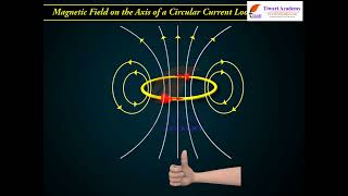
MAGNETIC FIELD ON THE AXIS OF A CIRCULAR CURRENT LOOP
Enroll to start learning
You’ve not yet enrolled in this course. Please enroll for free to listen to audio lessons, classroom podcasts and take practice test.
Interactive Audio Lesson
Listen to a student-teacher conversation explaining the topic in a relatable way.
Biot-Savart Law and Magnetic Fields
🔒 Unlock Audio Lesson
Sign up and enroll to listen to this audio lesson

Today, we explore how magnetic fields are calculated, particularly the magnetic field on the axis of a circular current loop, using the Biot-Savart law. Can anyone recall what the Biot-Savart law states?

It's about how the magnetic field is produced by a current element?
Exactly! It describes how each infinitesimal current element produces a magnetic field at a point in space. Now, for a circular loop, we want to calculate the total magnetic field at point P along the axis. What vectors do we need to consider?

The displacement vector from the current element to point P, right?
Correct! And this relationship can be represented mathematically. The infinitesimal magnetic field dB due to the current Idl is expressed in the formula we use for integration.

What happens to the components that are not along the axis?
Great question! Those components cancel each other out when we sum them over the loop, leaving us with only the x-component contributing to the field along the axis. Let’s capture this!
Calculating the Magnetic Field
🔒 Unlock Audio Lesson
Sign up and enroll to listen to this audio lesson

To derive the magnetic field at point P, we start with the vector expression of the Biot-Savart law. Can anyone represent it mathematically?

$$dB = \frac{\mu_0 Idl \times r}{4 \pi r^3}$$
Perfect! Remember, we need to integrate this over the entire loop. Each current element contributes a part to the total magnetic field. Who can summarize what we do next?
We calculate the distance squared which is $$x^2 + R^2$$, right?
Exactly! And using that in the integration helps us simplify our expression for B at point P.
So, does it mean the distance affects how strong the magnetic field is?
Right again! The further you go along the axis from the center of the loop, the weaker the magnetic field becomes. Let's summarize the magnetic field equation we derive.
Direction of the Magnetic Field
🔒 Unlock Audio Lesson
Sign up and enroll to listen to this audio lesson
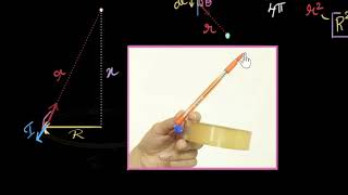
Now that we have our formula for B, how do we determine its direction?
Isn't it by using the right-hand thumb rule?
Exactly right! Curl your fingers in the direction of current flow, and your thumb points in the direction of the magnetic field at the center.
Will the direction of B change depending on which way the current flows?
Yes! If you reverse the current's direction, the magnetic field direction also reverses. This is important to remember when working with electric circuits.
So does this mean magnetic fields create loops, like with compass needles?
Exactly! Magnetic field lines are closed loops, always returning to their source. Great observations today! Let's recap the significance of the Biot-Savart law for current loops.
Introduction & Overview
Read summaries of the section's main ideas at different levels of detail.
Quick Overview
Standard
This section explores how to calculate the magnetic field produced by a circular current loop at a point along its axis. It uses the principles established by the Biot-Savart law and evaluates the magnetic field components from each infinitesimal current element.
Detailed
Detailed Summary
In Section 4.5, the magnetic field generated at a point along the axis of a circular current loop is evaluated. The circular loop, positioned in the XY-plane with its center at the origin (O) and radius R, carries a steady current (I). To determine the magnetic field (B) at a point located along the axis at a distance x from the center, we use the Biot-Savart law. The magnetic field dB due to an infinitesimal current element (Idl) is described by the formula:
$$
dB = \frac{\mu_0 I \, dl \times r}{4 \pi r^3}
$$
Where r is the displacement vector from dl to the axial point P, with its magnitude depending on both x and R. Integrating these contributions allows us to calculate the resultant magnetic field along the axis, revealing how the geometry of the loop shapes the magnetic field's distribution. The resulting formula for the magnetic field at any point on the axis and specifically at the center of the loop are provided:
$$
B = \frac{\mu_0 I R^2}{2 \left( x^2 + R^2 \right)^{3/2}}, \
B \text{ at the center: } B = \frac{\mu_0 I}{2R}
$$
These equations highlight not just the relationship between current, distance, and the resultant magnetic field, but also the underlying symmetry in the field created by current loops. The section also introduces the right-hand thumb rule for determining the direction of the magnetic field, thereby connecting the theoretical calculations with practical applications.
Youtube Videos


Audio Book
Dive deep into the subject with an immersive audiobook experience.
Introduction to Magnetic Field Due to a Circular Coil
Chapter 1 of 5
🔒 Unlock Audio Chapter
Sign up and enroll to access the full audio experience
Chapter Content
In this section, we shall evaluate the magnetic field due to a circular coil along its axis. The evaluation entails summing up the effect of infinitesimal current elements (I dl) mentioned in the previous section. We assume that the current I is steady and that the evaluation is carried out in free space (i.e., vacuum).
Detailed Explanation
This chunk introduces the aim of the section: to calculate the magnetic field generated by a circular coil when viewed from its axis. It signifies that, to find this magnetic field, we will consider many small segments of the coil, each carrying a current. The assumption is that the current is constant and we’re observing it in a vacuum where external factors do not affect the results.
Examples & Analogies
Think of the circular coil like a group of small people standing in a circle, all of them holding hands and pulling with equal strength. This collective effort influences what happens in the center of this circle, much like how the small current segments influence the magnetic field at the center of the coil.
Geometrical Setup
Chapter 2 of 5
🔒 Unlock Audio Chapter
Sign up and enroll to access the full audio experience
Chapter Content
Fig. 4.9 depicts a circular loop carrying a steady current I. The loop is placed in the plane with its centre at the origin O and has a radius R. The x-axis is the axis of the loop. We wish to calculate the magnetic field at the point P on this axis. Let x be the distance of P from the centre O of the loop.
Detailed Explanation
Here, the chunk discusses the geometry involved in the situation being analyzed. We have a circular loop with a radius R and a current I flowing through it. The center of the loop is at the origin of a coordinate system, and we are particularly interested in the magnetic field effect at point P, which lies along the x-axis at a distance x from the center. This setup is crucial for calculations later as it provides clear parameters for equations.
Examples & Analogies
Imagine drawing a circle on a piece of paper. The center is like a busy city, and the area within the circle represents a neighborhood. As people in the neighborhoods move (like our current), they impact what happens in the city center. Similarly, each part of the loop contributes to the magnetic field at point P.
Calculating the Magnetic Field
Chapter 3 of 5
🔒 Unlock Audio Chapter
Sign up and enroll to access the full audio experience
Chapter Content
Consider a conducting element dl of the loop. The magnitude dB of the magnetic field due to dl is given by the Biot-Savart law [Eq. 4.7(a)].
dB = µ₀(I dl × r) / (4π r³)
where r² = x² + R². Further, any element of the loop will be perpendicular to the displacement vector from the element to the axial point.
Detailed Explanation
In this section, we use the Biot-Savart law, which provides a way to calculate the magnetic field generated by a small segment of current. The formula states that the magnetic field contribution dB from a small segment dl of the loop at point P is dependent on the current (I), the small length of the wire (dl), and the distance (r) from the segment to point P. Note that r depends on both x and R, the radius of the loop. This setup allows us to calculate the total magnetic field by integrating all these small contributions.
Examples & Analogies
Imagine each person (the current element) holding onto a stick (the dl) which pushes against a nearby object. The strength of the push (the dB) depends on how strong they are pulling (the current I) and how far they are from the object. To know the total impact on the object at the center (point P), we need to consider the contributions from all the people around the circle.
Direction of the Magnetic Field
Chapter 4 of 5
🔒 Unlock Audio Chapter
Sign up and enroll to access the full audio experience
Chapter Content
The direction of dB is shown in Fig. 4.9. It is perpendicular to the plane formed by dl and r. It has an x-component dBx and a component perpendicular to the x-axis, dB⊥. When the components perpendicular to the x-axis are summed over, they cancel out and we obtain a null result.
Detailed Explanation
This part of the evaluation deals with the directionality of the magnetic field created by each current segment of the loop. According to the right-hand rule, the direction of the magnetic field dB is determined to be perpendicular to the plane created by the current segment dl and the line connecting the segment to point P (r). When analyzing contributions along the axis and those that are perpendicular, it becomes apparent that the perpendicular influences cancel each other out, leaving only the contribution along the axis of interest.
Examples & Analogies
Consider rotating a fan in a room. The blades exert wind (like the magnetic field) in various directions. If you look closely, some parts of the wind might push against the walls, but those forces cancel each other out, while only the wind that moves directly forward (along the specified direction) matters to the person standing in front of the fan.
Integration to Find Total Magnetic Field
Chapter 5 of 5
🔒 Unlock Audio Chapter
Sign up and enroll to access the full audio experience
Chapter Content
Thus, only the x-component survives. The net contribution along x-direction can be obtained by integrating dBx over the loop. The summation of elements dl over the loop yields 2πR, the circumference of the loop. Thus, the magnetic field at P due to entire circular loop is
B = (μ₀I R²) / [2(x² + R²)³/2].
Detailed Explanation
This final chunk sums it all together by integrating the x-component of the magnetic field over the entire loop. We approximate the contributions along the axis and sum the entire contribution into a single equation. From this, we find the total magnetic field expression at point P on the axis, creating a relationship based on the current, geometry of the loop, and distance from the center.
Examples & Analogies
Picture collecting all the wind gusts from every blade of a fan into one large blast you would feel directly in front of it. You would take into account every tiny push from each blade to calculate the total push of air (the total magnetic field) felt at your face. Just as each gust combines to create one strong wind, each piece’s contribution combines to give us the total magnetic effect at point P.
Key Concepts
-
Biot-Savart Law: It governs the magnetic field produced by a segment of current.
-
Integration of Magnetic Field: The total field from all current elements is determined through integration.
-
Direction of Magnetic Field: It follows the right-hand rule based on the direction of current flow.
Examples & Applications
The magnetic field at the center of a loop is given by $$B = \frac{\mu_0 I}{2R}$$.
The resultant magnetic field at a point along the axis is computed using $$B = \frac{\mu_0 I R^2}{2(x^2 + R^2)^{3/2}}$$.
Memory Aids
Interactive tools to help you remember key concepts
Rhymes
A loop would spin and spin, any increase − it's a win!
Stories
Once, a little wire loop was so full of current, it created magnetic fields that danced around!
Memory Tools
Use R-R-B: Right Hand - Roll Fingers - Behold direction of B!
Acronyms
B - Biot, I - Current, R - Radius, M - Moment.
Flash Cards
Glossary
- BiotSavart Law
A law that describes the magnetic field generated by an electric current element.
- Magnetic Field
A vector field that exerts a force on moving charges and magnetic dipoles.
- Current Loop
A closed loop of wire through which electric current flows, producing a magnetic field.
- RightHand Thumb Rule
A mnemonic used to determine the direction of the magnetic field around a current-carrying conductor.
- Magnetic Moment
A vector quantity that represents the strength and direction of a magnetic source.
Reference links
Supplementary resources to enhance your learning experience.