
THE MOVING COIL GALVANOMETER
Enroll to start learning
You’ve not yet enrolled in this course. Please enroll for free to listen to audio lessons, classroom podcasts and take practice test.
Interactive Audio Lesson
Listen to a student-teacher conversation explaining the topic in a relatable way.
Introduction to Moving Coil Galvanometer
🔒 Unlock Audio Lesson
Sign up and enroll to listen to this audio lesson

Welcome, class! Today, we will discuss an important instrument in electrical measurements—the moving coil galvanometer. Can anyone tell me what a galvanometer is used for?

Isn't it used to measure current?
Absolutely! The galvanometer measures current, and it can also be used as a voltmeter. Let’s delve into how it works. The MCG consists of a coil that rotates within a magnetic field.

How does the coil rotate?
Great question! When electric current flows through the coil, it experiences a magnetic torque. This is expressed mathematically as \(\tau = N I AB\).

What do those symbols mean?
Good point! Here, \(N\) is the number of turns in the coil, \(I\) is the current passing through, \(A\) is the area of the coil, and \(B\) is the magnetic field strength.

So, the torque depends on those factors?
Exactly! The more turns or a stronger current increases the torque acting on the coil. Now let’s summarize: The MCG uses a coil in a magnetic field to measure current through its rotational deflection.
Conversion to Ammeter and Voltmeter
🔒 Unlock Audio Lesson
Sign up and enroll to listen to this audio lesson

Now that we understand how an MCG works, let’s discuss how we can convert it into an ammeter or voltmeter. Who knows how we might do that?
Do we need to add resistances?
Correct! To use the MCG as an ammeter, we connect a small shunt resistance in parallel. This allows most of the current to bypass the galvanometer while still measuring the current accurately.
What about using it as a voltmeter?
Excellent! For a voltmeter, we connect a large resistance in series with the galvanometer. This way, it draws a very small current from the circuit, minimizing any disturbance.
And how do we express these relationships mathematically?
For current sensitivity, we can write it as \(f_s = \frac{NAB}{k}\), where \(f_s\) is the sensitivity. For voltage sensitivity, it can be expressed similarly.
Does increasing the sensitivity change anything else?
Good question! Increasing the sensitivity through more turns also impacts the resistance of the galvanometer. That’s an important balance to consider!
Practical Applications
🔒 Unlock Audio Lesson
Sign up and enroll to listen to this audio lesson
Let's talk about practical applications of the moving coil galvanometer. Why do you think this instrument is considered useful?
It can be used to test electrical circuits and measure components, right?
Exactly! It can detect current flow or measure voltage drops in circuits. It's vital for troubleshooting and analyzing circuits.
Is it accurate for all current levels?
The MCG is very sensitive, able to pick up microamperes of current. However, for measuring higher currents, it’s essential to use a shunt to prevent damage.
Can we use it in DC and AC?
Mostly in DC circuits, but modified MCGs can also measure AC by averaging the values over time! This adaptability is invaluable.
What’s a final takeaway about the MCG?
The MCG is crucial for precision in electrical measurements, allowing us to quantify current and voltage with high accuracy while being adaptable for various measuring contexts.
Introduction & Overview
Read summaries of the section's main ideas at different levels of detail.
Quick Overview
Standard
This section provides an overview of the moving coil galvanometer (MCG), explaining its structure, working principle, and the mathematical relationship governing its measurements. It highlights how the MCG can be adapted for both ammeter and voltmeter applications.
Detailed
Detailed Summary of The Moving Coil Galvanometer
The Moving Coil Galvanometer (MCG) is an essential device in electrical measurements, particularly for assessing current and voltage. It operates based on the interaction between a coil of wire and a magnetic field. The galvanometer consists of a coil, wound with many turns, positioned in a uniform radial magnetic field, created by a cylindrical soft iron core. The magnetic torque generated on the coil is given by the relationship:
\[ \tau = N I AB \]
Where:
- \(\tau\) is the torque,
- \(N\) is the number of turns,
- \(I\) is the current,
- \(A\) is the area of the coil, and
- \(B\) is the magnetic field strength.
As current flows through the coil, it experiences a force due to this torque, which causes it to rotate. A spring counteracts this torque, leading to a steady angular deflection, which can be measured on a scale via a pointer. The angular deflection equation can be expressed as:
\[ \phi = \frac{NAB}{k}I \]
Where \(k\) is the spring's torsional constant. To convert the galvanometer into an ammeter or voltmeter, additional resistances are employed. A shunt resistance allows the galvanometer to measure current more accurately without significantly affecting the overall circuit, while a series resistance enables voltage measurement, ensuring minimal current draw to avoid disturbance in the circuit's original state.
Overall, the MCG is pivotal in practical electrical applications due to its sensitivity and adaptability.
Youtube Videos


Audio Book
Dive deep into the subject with an immersive audiobook experience.
Introduction to the Moving Coil Galvanometer
Chapter 1 of 7
🔒 Unlock Audio Chapter
Sign up and enroll to access the full audio experience
Chapter Content
Currents and voltages in circuits have been discussed extensively in Chapters 3. But how do we measure them? How do we claim that current in a circuit is 1.5 A or the voltage drop across a resistor is 1.2 V? Figure 4.20 exhibits a very useful instrument for this purpose: the moving coil galvanometer (MCG).
Detailed Explanation
The moving coil galvanometer is an instrument designed to measure electric currents and voltages in circuits. It operates on the principle of electromagnetism—specifically, the interaction between magnetic fields and electric currents. By detecting the angular deflection of a coil in a magnetic field due to the flow of current, it provides an indication of the current's magnitude.
Examples & Analogies
Think of the galvanometer like a measuring stick used to gauge the amount of fluid in a container. Just as a measuring stick can tell you how much fluid is present based on its level, a galvanometer indicates the strength of an electric current based on how much the coil moves in response to it.
Construction and Working Principle
Chapter 2 of 7
🔒 Unlock Audio Chapter
Sign up and enroll to access the full audio experience
Chapter Content
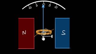
The galvanometer consists of a coil, with many turns, free to rotate about a fixed axis, in a uniform radial magnetic field. There is a cylindrical soft iron core which not only makes the field radial but also increases the strength of the magnetic field.
Detailed Explanation
The moving coil galvanometer features a coil composed of multiple turns of wire, allowing for significant electromagnetic induction. When a current flows through this coil, it generates a magnetic field. Meanwhile, the external uniform magnetic field interacts with this coil, producing a torque that causes the coil to rotate. This rotation is proportional to the current flowing through the coil.
Examples & Analogies
Imagine spinning a bicycle wheel. The spokes of the wheel represent the loops of wire in the galvanometer. When the wheel turns, it shows how fast you're going, just like the rotating coil of the galvanometer indicates the strength of the current.
Torque and Deflection
Chapter 3 of 7
🔒 Unlock Audio Chapter
Sign up and enroll to access the full audio experience
Chapter Content
When a current flows through the coil, a torque acts on it. This torque is given by Eq. (4.20) to be τ = NIAB where the symbols have their usual meaning. Since the field is radial by design, we have taken sin θ = 1 in the above expression for the torque.
Detailed Explanation
When current flows through the coil, it experiences torque, which is the rotational force acting on it. The torque can be calculated using the formula τ = NIAB, where N is the number of turns, I is the current, A is the area of the coil, and B is the strength of the magnetic field. Since the magnetic field is designed to be uniform and radial, the angle θ is effectively 90 degrees, making sin θ equal to 1.
Examples & Analogies
Consider opening a door. The torque you apply to the door handles when you push on it affects how far the door swings open. Similarly, the electric current creates a 'push' (torque) on the coil, which makes it 'swing' (rotate) to indicate the current value.
Spring Balance and Equilibrium
Chapter 4 of 7
🔒 Unlock Audio Chapter
Sign up and enroll to access the full audio experience
Chapter Content
A spring S provides a counter torque kφ that balances the magnetic torque NIAB; resulting in a steady angular deflection φ. In equilibrium kφ = NI AB.
Detailed Explanation
To achieve a stable reading, the galvanometer incorporates a spring that counteracts the torque from the magnetic field acting on the coil. As the coil rotates due to current, a balance is established when the torsional force exerted by the spring (kφ) equals the torque produced by the current in the coil (NIAB). This is known as the equilibrium position where the needle points to a definitive current value on the scale.
Examples & Analogies
Think of a seesaw with weights on either side. If one side is heavier, the seesaw tips, but if you add enough weight on the lighter side, it can balance out. The spring in the galvanometer acts like the weight that balances the seesaw, ensuring the reading remains stable.
Using the Galvanometer as an Ammeter
Chapter 5 of 7
🔒 Unlock Audio Chapter
Sign up and enroll to access the full audio experience
Chapter Content
The galvanometer cannot as such be used as an ammeter to measure the value of the current in a given circuit. This is for two reasons: (i) Galvanometer is a very sensitive device, it gives a full-scale deflection for a current of the order of µA. (ii) For measuring currents, the galvanometer has to be connected in series, and as it has a large resistance, this will change the value of the current in the circuit.
Detailed Explanation
While the galvanometer provides accurate readings for very small currents, it is not practical as an ammeter because it cannot handle larger currents effectively. Due to its sensitivity, connecting it directly to a circuit can cause it to exceed its operational limits, leading to inaccurate measurements.
Examples & Analogies
Consider a tiny scale designed to weigh small pearls. If you tried to place a bucket of sand on it, it would be overwhelmed and probably break. Similarly, the galvanometer is excellent for fine measurements, but it can't simply be plugged directly into strong currents.
Shunt Resistance for Ammeter Functionality
Chapter 6 of 7
🔒 Unlock Audio Chapter
Sign up and enroll to access the full audio experience
Chapter Content
To overcome these difficulties, one attaches a small resistance r, called shunt resistance, in parallel with the galvanometer coil; so that most of the current passes through the shunt.
Detailed Explanation
To convert the galvanometer into an effective ammeter, a shunt resistor is placed in parallel with the device. This design allows the majority of the current to bypass the galvanometer, ensuring that the sensitive instrument only measures a small, manageable fraction of the current in the circuit, thus preventing damage and ensuring accurate readings.
Examples & Analogies
Imagine using a water flow valve to protect a delicate measuring cup in a pipeline. The valve allows most of the water to flow past safely while controlling the tiny amount that reaches the delicate cup, protecting it from overflow. Similarly, the shunt protects the galvanometer.
Conversion to Voltmeter
Chapter 7 of 7
🔒 Unlock Audio Chapter
Sign up and enroll to access the full audio experience
Chapter Content
The galvanometer can also be used as a voltmeter to measure the voltage across a given section of the circuit. For this it must be connected in parallel with that section of the circuit.
Detailed Explanation
The galvanometer can be adapted to measure voltage by connecting it in parallel with the circuit component across which the voltage is to be measured. This configuration allows the galvanometer to sense the potential difference while drawing minimal current to ensure it does not affect the circuit operations significantly.
Examples & Analogies
Consider a fly landing on a scale. It will read the weight without significantly changing the weight of the object being measured. Similarly, when the galvanometer measures voltage, it takes a small 'sip' of current so that the overall circuit behavior remains mostly unchanged.
Key Concepts
-
Torque: The force that causes rotation in the galvanometer's coil when current flows.
-
Current Sensitivity: The responsiveness of the galvanometer to changes in current, defined by its dimensions and resistance.
-
Voltage Sensitivity: The responsiveness related to measuring voltage defined by added resistances in the galvanometer circuit.
Examples & Applications
An example of an MCG measuring a current of 1.5 A, balancing the torque due to the current with a spring's restoring torque.
Using a shunt resistance of 0.01 Ω to measure a 10 A current without damaging the galvanometer.
Memory Aids
Interactive tools to help you remember key concepts
Rhymes
When current flows, the coil turns round, / In fields of forces, sensitivity is found.
Stories
Imagine a coil dancing with the rhythm of current in a magnetic field—a dance that tells you so much about voltage and current in your electric circuits.
Memory Tools
Remember 'GAS': Galvanometer, Ammeter, Shunt—think of how these terms are linked in measuring current.
Acronyms
MCG - Moving Coil Galvanometer
'Measure Current Gracefully' to recall its function.
Flash Cards
Glossary
- Moving Coil Galvanometer (MCG)
A device used for measuring electrical current, utilizing the principle of torque in a magnetic field.
- Torque
A measure of the force that causes an object to rotate about an axis.
- Resistance
The opposition to the flow of electric current, measured in ohms (Ω).
- Shunt Resistance
A small resistance used in parallel with galvanometers to measure larger currents.
- Torsional Constant (k)
A measure of the restoring torque per unit twist for the spring in a galvanometer.
Reference links
Supplementary resources to enhance your learning experience.