
CMOS NAND and NOR Gates
Enroll to start learning
You’ve not yet enrolled in this course. Please enroll for free to listen to audio lessons, classroom podcasts and take practice test.
Interactive Audio Lesson
Listen to a student-teacher conversation explaining the topic in a relatable way.
Understanding CMOS NAND Gates
🔒 Unlock Audio Lesson
Sign up and enroll to listen to this audio lesson

Let's start by discussing the CMOS NAND gate. Can anyone tell me how a NAND gate works?

I think it outputs low only when both inputs are high?
Exactly! When both inputs are high, the NMOS transistors pull the output to ground, making it low. In all other cases, at least one PMOS is conducting, pulling the output high. This is a key feature of NAND gates.

What's the truth table for the NAND gate?
Great question! It looks like this: when both inputs are high, output is low; otherwise, the output is high. So, for inputs (0,0), (0,1), (1,0), we get output high, and for (1,1), the output is low.

Can you give us a memory aid to remember this?
Of course! Remember 'Not AND' – whenever there’s a '1 AND 1', think 'no' for output. That helps in recalling the NAND function.

So if I have inputs (1, 0), I would think the output is 1?
Correct! Well done! To summarize, a NAND gate is a combination of PMOS and NMOS that outputs low only when both inputs are high.
Exploring CMOS NOR Gates
🔒 Unlock Audio Lesson
Sign up and enroll to listen to this audio lesson

Now let's discuss the CMOS NOR gate. What do you know about its operation?
I remember that it outputs high only when all inputs are low!
That's correct! The NOR gate only outputs a high signal when both inputs are low. Both NMOS transistors will be off, and the PMOS transistors will turn on, pulling the output high.
What's the truth table for the NOR gate?
The truth table for a NOR gate is quite straightforward: with inputs (0,0), the output is high (1); with (0,1), (1,0), and (1,1), the output is low (0).
Can we use a memory aid for the NOR gate too?
Absolutely! You can say ‘Not OR’ – which helps to remember that with '1' present in either input, the output cannot be '1'. Hence, both must be '0' to get a high output.
So with inputs (1, 0), the output would be 0?
Yes, exactly! To wrap up, just remember that the NOR gate only gives a high output when all inputs are low.
Applications and Importance of NAND and NOR Gates
🔒 Unlock Audio Lesson
Sign up and enroll to listen to this audio lesson
Let's connect these concepts to real-world applications. Why do you think NAND and NOR gates are termed 'universal'?
Because you can make any kind of logic gate using them?
Exactly! NAND and NOR gates are universal because you can combine them to form other types of gates, like AND, OR, etc. This property makes them essential in circuit designs.
How are they used in computer circuits?
They are foundational components used in processors and memory devices. By combining them in various configurations, we can build complex logical functions required for computational tasks.
So they really are the backbone of digital electronics?
Absolutely! And their efficiency in power use, especially CMOS design, makes them even more critical in portable and energy-efficient devices.
Thanks for explaining this clearly!
You're welcome! Remember, the concepts of NAND and NOR gates are foundational for understanding more complex digital systems.
Introduction & Overview
Read summaries of the section's main ideas at different levels of detail.
Quick Overview
Standard
In this section, we explore the structure and functionality of CMOS NAND and NOR gates. These gates are fundamental components in digital electronics, with the ability to pull output high or low based on input conditions, making them versatile in logic circuit design.
Detailed
Detailed Summary of CMOS NAND and NOR Gates
CMOS NAND and NOR gates are critical components of digital electronics, built using complementary metal-oxide-semiconductor (CMOS) technology. They consist of NMOS and PMOS transistors arranged to perform fundamental binary operations. The NAND gate operates by turning the output low (0) when both inputs are high (1), while the NOR gate outputs high (1) only when both inputs are low (0). Both gates are universal gates, meaning they can be combined to perform any logical function, making them invaluable in circuit design. Understanding their structures, operational principles, and truth tables is crucial for those studying digital circuit design and logic systems.
Youtube Videos


Audio Book
Dive deep into the subject with an immersive audiobook experience.
Introduction to CMOS NAND and NOR Gates
Chapter 1 of 5
🔒 Unlock Audio Chapter
Sign up and enroll to access the full audio experience
Chapter Content
The NAND and NOR gates are two fundamental digital gates that can be implemented using CMOS transistors. Both gates are universal gates, meaning they can be combined to implement any other logic function.
Detailed Explanation
NAND and NOR gates are critical components in digital logic design. They are called 'universal gates' because you can construct any other type of gate—like AND, OR, or NOT—using just these two types. Understanding NAND and NOR gates is essential as they form the foundation of various digital circuits and systems.
Examples & Analogies
Think of NAND and NOR gates as the universal toolkit in a handyman's shed. Just like you can use a hammer and nail to build a variety of structures—like a table, chair, or shelf—you can combine NAND and NOR gates to create all sorts of logical operations in digital circuits.
CMOS NAND Gate Operation
Chapter 2 of 5
🔒 Unlock Audio Chapter
Sign up and enroll to access the full audio experience
Chapter Content
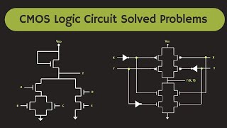
The CMOS NAND gate is made by connecting two NMOS transistors in series and two PMOS transistors in parallel. The NMOS transistors pull the output to ground when both inputs are high, while the PMOS transistors pull the output to Vdd when at least one input is low.
● Operation:
○ When both inputs are high (1), both NMOS transistors turn on, pulling the output to low (0). Both PMOS transistors are off.
○ In all other cases (one or both inputs are low), the output will be high (1) due to the complementary action of the PMOS transistors.
Detailed Explanation
A CMOS NAND gate consists of two types of transistors—NMOS and PMOS—arranged specifically to perform a logical NAND function. When both inputs are high (1), the NMOS transistors connect the output to ground, resulting in a low output (0). However, if either input is low (0), the PMOS transistors enable a path to the supply voltage (Vdd), giving a high output (1). This design minimizes power consumption and utilizes the complementary action of both transistor types effectively.
Examples & Analogies
Imagine a light switch that requires two buttons to be pressed to turn off the light. If both buttons are pressed (both inputs high), the light turns off. But if either button is not pressed (one or both inputs low), the light remains on. This is similar to how the NAND gate operates: both inputs need to be high to produce a low output.
CMOS NAND Gate Truth Table
Chapter 3 of 5
🔒 Unlock Audio Chapter
Sign up and enroll to access the full audio experience
Chapter Content
6.3.2 CMOS NAND Gate Truth Table
Input Input Output
A B Vout
0 0 1
0 1 1
1 0 1
1 1 0
Detailed Explanation
The truth table for the CMOS NAND gate systematically outlines how the output changes based on different combinations of the inputs (A and B). There are four possible combinations of input states:
1. When both inputs are 0 (0, 0), the output is 1.
2. When one input is 1 and the other is 0 (0, 1 or 1, 0), the output remains 1.
3. Only when both inputs are 1 (1, 1), the output drops to 0. This clearly demonstrates the NAND operation.
Examples & Analogies
Think of a 'no entry' sign on a door: if both doormen (representing the inputs) are present (both 1), the door is shut (output is 0). However, if at least one doorman is absent (one or both inputs are 0), the door is open (output is 1).
CMOS NOR Gate Operation
Chapter 4 of 5
🔒 Unlock Audio Chapter
Sign up and enroll to access the full audio experience
Chapter Content
The CMOS NOR gate is made by connecting two NMOS transistors in parallel and two PMOS transistors in series. The NMOS transistors pull the output to ground when either of the inputs is high, while the PMOS transistors pull the output to Vdd only when both inputs are low.
● Operation:
○ When both inputs are low (0), both PMOS transistors turn on, pulling the output to high (1). Both NMOS transistors are off.
○ When either or both inputs are high (1), the output will be low (0) due to the conducting NMOS transistors.
Detailed Explanation
In a CMOS NOR gate, the configuration of the NMOS and PMOS transistors functions distinctly compared to the NAND gate. Here, the NMOS transistors are set up in parallel to quickly pull the output to ground if any input is high. Conversely, the PMOS transistors are arranged in series to pull the output up to Vdd only when both inputs are low. This behavior is essential for implementing logical NOR functions, preserving efficiency.
Examples & Analogies
Consider a fire alarm system that sounds only when no smoke detectors (inputs) are operational. If both detectors are not detecting smoke (both inputs low), the alarm goes off (output is high). But if any detector senses smoke (any input high), the alarm is quiet (output is low). This is akin to how a NOR gate operates, only activating under specific conditions.
CMOS NOR Gate Truth Table
Chapter 5 of 5
🔒 Unlock Audio Chapter
Sign up and enroll to access the full audio experience
Chapter Content
6.3.4 CMOS NOR Gate Truth Table
Input Input Output
A B Vout
0 0 1
0 1 0
1 0 0
1 1 0
Detailed Explanation
The truth table for the CMOS NOR gate illustrates how the output is influenced by the various combinations of its inputs. The output is high (1) only when both inputs are low (0, 0). If either input is high (0, 1; 1, 0; or 1, 1), the output remains low (0). This core characteristic defines the NOR logical operation.
Examples & Analogies
Imagine a backup generator that only powers a house when the main electricity is off. If the main power is functioning (any input high), the generator (output) is off. Only when the main power fails (both inputs low) does the generator kick in and power the house.
Key Concepts
-
CMOS Technology: The fundamental technology that allows for the construction of logic gates with low power consumption.
-
NAND Gate: Produces a low output only when both inputs are high.
-
NOR Gate: Produces a high output only when both inputs are low.
-
Universal Gates: Both NAND and NOR can be used to create any logic function.
Examples & Applications
For a NAND gate with inputs (0, 1), the output is 1.
For a NOR gate with inputs (0, 0), the output is 1.
Memory Aids
Interactive tools to help you remember key concepts
Rhymes
NAND is grand, when both are high, it won't comply; NOR, if they're low, it lets light glow.
Stories
Imagine a security lock (NAND) that only opens when both keys are inserted. A separate light (NOR) only shines when no one is around.
Memory Tools
Remember 'Not AND' for NAND and 'Not OR' for NOR, to help recall their output conditions.
Acronyms
NAND
'Not And'. NOR
Flash Cards
Glossary
- CMOS
Complementary Metal-Oxide-Semiconductor, a technology for constructing integrated circuits, including digital logic gates.
- NAND Gate
A digital logic gate that outputs low only when both inputs are high; otherwise outputs high.
- NOR Gate
A digital logic gate that outputs high only when both inputs are low; otherwise outputs low.
- Truth Table
A table that summarizes the output of a logic gate for all possible input combinations.
Reference links
Supplementary resources to enhance your learning experience.