
CMOS NAND Gate Truth Table
Enroll to start learning
You’ve not yet enrolled in this course. Please enroll for free to listen to audio lessons, classroom podcasts and take practice test.
Interactive Audio Lesson
Listen to a student-teacher conversation explaining the topic in a relatable way.
Introduction to CMOS NAND Gate
🔒 Unlock Audio Lesson
Sign up and enroll to listen to this audio lesson

Today, we are focusing on the CMOS NAND gate. Let's start by discussing its structure. Can anyone tell me how a NAND gate is constructed?

Isn't it made up of NMOS and PMOS transistors?
Exactly! The NAND gate has two NMOS transistors in series and two PMOS transistors in parallel. Can anyone explain what happens to the output when both inputs are high?

The output will be low, right? Only when both inputs are high.
Correct! This unique behavior is essential for creating logical connections in circuits.
Understanding the Truth Table
🔒 Unlock Audio Lesson
Sign up and enroll to listen to this audio lesson

Now, let's look at the truth table for the NAND gate. Can someone summarize what it indicates?

The output is only zero when both A and B are one; otherwise, it's one.
That's right! This table is a snapshot of the NAND gate's function. Let’s reinforce this by recalling the truth table together: what is the output when A is 0 and B is 1?

The output will be one.
Great! Let's practice saying these combinations a few times to help memorize them.
Applications of NAND Gates
🔒 Unlock Audio Lesson
Sign up and enroll to listen to this audio lesson
Why do you think NAND gates are considered universal gates?
Because we can create any other logic gate using NAND gates!
Absolutely! This versatility makes them invaluable in digital electronics. Does anyone have examples of circuits that utilize NAND gates?
I think they can be used in creating flip-flops and also in building arithmetic circuits.
Correct! Remember, any logic function can be constructed using just NAND gates, which makes them an essential part of logic design.
Review and Reinforcement
🔒 Unlock Audio Lesson
Sign up and enroll to listen to this audio lesson
Let’s summarize what we learned today about the CMOS NAND gate and its truth table. Who can balance the inputs and outputs of the NAND gate once more?
Sure! A and B are both 0... the output is 1!
Excellent! Can anyone tell me what the output is when both A and B are 1 again?
The output is 0.
Great job, everyone! Knowing this table helps us understand not just NAND gates but digital circuits as a whole. Keep reviewing these key points!
Introduction & Overview
Read summaries of the section's main ideas at different levels of detail.
Quick Overview
Standard
The CMOS NAND gate is essential in digital logic, functioning as a universal gate capable of combining to implement any logic function. Its truth table outlines the relationship between its inputs and output.
Detailed
CMOS NAND Gate Truth Table
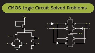
The CMOS NAND gate is a universal gate composed of two NMOS transistors in series and two PMOS transistors in parallel. This configuration allows the NAND gate to function efficiently within digital logic circuits. The truth table for the CMOS NAND gate is crucial for understanding how it processes binary inputs and determines its output.
Key Points of the NAND Gate:
- Inputs and Outputs: The NAND gate has two inputs (A and B) and one output (V_out).
- Operation: The output is low (0) only when both inputs are high (1).
This characteristic makes the NAND gate fundamental in digital electronics, allowing it to perform operations that other gates can emulate when combined.
Here is the truth table:
| Input A | Input B | Output V_out |
|---|---|---|
| 0 | 0 | 1 |
| 0 | 1 | 1 |
| 1 | 0 | 1 |
| 1 | 1 | 0 |
Understanding this truth table is critical for designing and analyzing digital circuits, making the NAND gate one of the most significant logical components.
Youtube Videos


Audio Book
Dive deep into the subject with an immersive audiobook experience.
NAND Gate Input Combinations
Chapter 1 of 2
🔒 Unlock Audio Chapter
Sign up and enroll to access the full audio experience
Chapter Content
| Input | Input | Output |
|---|---|---|
| A | B | Vout |
| 0 | 0 | 1 |
| 0 | 1 | 1 |
| 1 | 0 | 1 |
| 1 | 1 | 0 |
Detailed Explanation
The NAND gate truth table lists all possible input combinations and their corresponding output. For a two-input NAND gate, the inputs A and B can each be 0 (low) or 1 (high). The output Vout is determined by the NAND logic, which states that the output is low (0) only when both inputs are high (1). In all other input combinations, the output is high (1). This behavior makes NAND gates different from AND gates, where the output would be high only when both inputs are high.
Examples & Analogies
You can think of a NAND gate like a light switch with two switches controlling the same light. The only time the light is off (output 0) is when both switches are turned on. In every other combination of switch positions (one or both are off), the light remains on (output 1).
Interpreting the Truth Table
Chapter 2 of 2
🔒 Unlock Audio Chapter
Sign up and enroll to access the full audio experience
Chapter Content
The truth table highlights four scenarios:
1. When both A and B are 0, the output Vout is 1.
2. When A is 0 and B is 1, the output Vout is 1.
3. When A is 1 and B is 0, the output Vout is 1.
4. When both A and B are 1, the output Vout is 0.
Detailed Explanation
Each row of the truth table corresponds to a specific condition of the input variables A and B. In the first three cases (0,0), (0,1), and (1,0), the output remains high (1) because at least one input is low. In the last case (1,1), both inputs are high, so the output drops to low (0). This clear distinction based on input conditions is vital in understanding how NAND gates function in digital circuits.
Examples & Analogies
Imagine a security system with two keys needed to unlock the gate. The gate only locks (output 0) when both keys are in the 'on' position (1). If at least one key is in the 'off' position (0), the gate remains unlocked (output 1).
Key Concepts
-
NAND Gate Operation: A NAND gate gives a low output only when both inputs are high.
-
Truth Table: The truth table summarizes the input-output relation of the NAND gate.
-
Universal Gates: NAND gates can be combined to create any other type of logic gate.
Examples & Applications
A common application of NAND gates is in constructing Latch circuits where multiple NAND gates can store binary states.
NAND gates can be used to build more complex circuits such as adders, counters, or multiplexers.
Memory Aids
Interactive tools to help you remember key concepts
Rhymes
If inputs are both one, the output is done; but if they’re not, the NAND keeps it hot!
Stories
Imagine a switch that only works when both buttons are pressed—if either button is off, the light shines bright! That's how a NAND gate works.
Memory Tools
NAND = Not AND. Remember, it flips the AND output!
Acronyms
NAND = 'Not And', highlights its operation.
Flash Cards
Glossary
- CMOS
Complementary Metal-Oxide-Semiconductor, a technology for constructing integrated circuits, including logic gates.
- NAND Gate
A digital logic gate that outputs a false (0) only when all its inputs are true (1).
- Truth Table
A mathematical table used in logic—showing the output of a logic gate for all possible input combinations.
- PMOS
A type of transistor that conducts when its gate voltage is low.
- NMOS
A type of transistor that conducts when its gate voltage is high.
Reference links
Supplementary resources to enhance your learning experience.