
CMOS NOR Gate Truth Table
Enroll to start learning
You’ve not yet enrolled in this course. Please enroll for free to listen to audio lessons, classroom podcasts and take practice test.
Interactive Audio Lesson
Listen to a student-teacher conversation explaining the topic in a relatable way.
Introduction to the CMOS NOR Gate
🔒 Unlock Audio Lesson
Sign up and enroll to listen to this audio lesson

Today, we're going to explore the CMOS NOR gate, which is essential in digital logic design. Can anyone explain what a NOR gate does?

It outputs true only when both inputs are false?
Exactly! The CMOS NOR gate outputs high only when both inputs are low. Let's look at the truth table to visualize this.

Can you remind us how PMOS and NMOS transistors interact in this gate?
Certainly! PMOS transistors conduct when inputs are low, while NMOS transistors conduct when inputs are high.
Understanding the Truth Table
🔒 Unlock Audio Lesson
Sign up and enroll to listen to this audio lesson

Let's analyze the truth table for the CMOS NOR gate. What do we expect when both inputs A and B are 0?

The output should be 1 since both inputs are low.
Great! And what happens if one of the inputs is 1? Can anyone share the output for A = 0, B = 1?

The output will be 0 because one input is high.
Correct! This shows how crucial understanding the input combinations is.
Significance of the CMOS NOR Gate
🔒 Unlock Audio Lesson
Sign up and enroll to listen to this audio lesson
Now, why do you think the NOR gate is considered a universal gate?
Because we can create any logic function using just NOR gates?
Exactly! NOR gates can be configured to perform any logic operation. This versatility is why they're fundamental in digital design.
So, do you mean we could even create AND or OR gates using NOR gates?
That's right! Familiarizing ourselves with their truth table supports understanding how to design complex circuits.
Introduction & Overview
Read summaries of the section's main ideas at different levels of detail.
Quick Overview
Standard
This section delves into the operation and truth table of the CMOS NOR gate. It explains the gate's configuration using NMOS and PMOS transistors and describes how the outputs are determined based on the input states.
Detailed
CMOS NOR Gate Truth Table
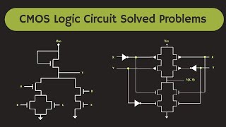
The CMOS NOR gate is implemented using complementary configurations of NMOS and PMOS transistors. In this section, we analyze the truth table of the CMOS NOR gate which depicts its logical behavior. The operation of this gate is defined as follows:
- When both inputs (A and B) are low (0), the PMOS transistors conduct, and the output (Vout) is pulled high (1).
- When either input is high (1), the NMOS transistors conduct and pull the output low (0).
This unique characteristic allows the NOR gate to serve as a building block for more complex logic functions and emphasizes the significance of understanding its operation in CMOS technology.
Youtube Videos


Audio Book
Dive deep into the subject with an immersive audiobook experience.
Introduction to the CMOS NOR Gate Truth Table
Chapter 1 of 1
🔒 Unlock Audio Chapter
Sign up and enroll to access the full audio experience
Chapter Content
Input | Input | Output
AA | BB | Vout
0 | 0 | 1
0 | 1 | 0
1 | 0 | 0
1 | 1 | 0
Detailed Explanation
The CMOS NOR gate truth table outlines how the gate behaves based on different input combinations (A and B). The output (Vout) is determined by the state of the inputs. When both inputs (A and B) are 0, the output is 1. If either or both inputs are 1, the output is 0. This means the NOR gate gives a high output only when all inputs are low.
Examples & Analogies
Imagine a light switch that is designed in such a way that the light only turns on when both switches are off. For example, think of a scenario with two switches: if both are off (0, 0), the light is on (1). If either switch is on (0, 1 or 1, 0 or 1, 1), the light is off (0). This is exactly how a NOR gate operates.
Key Concepts
-
CMOS NOR Gate: A digital gate that outputs true only when both inputs are false.
-
Truth Table: A representation of the output values based on all possible input combinations.
-
NMOS and PMOS Configuration: The arrangement of transistors in complementary logic to achieve desired output.
Examples & Applications
When inputs A = 0 and B = 0, the NOR gate outputs 1, showing it performs a negation on the inputs.
For inputs A = 1 and B = 0, the NOR gate outputs 0, demonstrating its fundamental behavior.
Memory Aids
Interactive tools to help you remember key concepts
Rhymes
If both inputs are low, up goes the show; if one can peak, down goes the sneak.
Stories
Imagine a gate at a party. Only when no one is present does the gate let people in. This relates to the NOR gate's logic.
Memory Tools
Naughty OR Nobody – Both must be nobody for the output to be 'yes'.
Acronyms
NOR
Negative Output unless Required (inputs are both zero).
Flash Cards
Glossary
- CMOS
Complementary Metal-Oxide-Semiconductor, a technology for constructing integrated circuits.
- NOR Gate
A digital logic gate that outputs high only when both inputs are low.
- Truth Table
A table used to define the output of a logic gate for all possible combinations of inputs.
- NMOS
N-type Metal-Oxide-Semiconductor, a transistor that conducts when a positive voltage is applied to its gate.
- PMOS
P-type Metal-Oxide-Semiconductor, a transistor that conducts when a negative voltage is applied to its gate.
Reference links
Supplementary resources to enhance your learning experience.