
CMOS XNOR Gate Truth Table
Enroll to start learning
You’ve not yet enrolled in this course. Please enroll for free to listen to audio lessons, classroom podcasts and take practice test.
Interactive Audio Lesson
Listen to a student-teacher conversation explaining the topic in a relatable way.
Introduction to CMOS XNOR Gate
🔒 Unlock Audio Lesson
Sign up and enroll to listen to this audio lesson

Today we're going to talk about the CMOS XNOR gate, which is a key component in digital circuits. Can anyone tell me what they think an XNOR gate does?

I think it might be similar to an XOR gate, right?
Great observation! Yes, it is similar, but the XNOR gate is the complement of the XOR gate. It outputs a high signal when the inputs are the same. Remember: 'XOR goes up, XNOR goes down' for equal inputs!

So, if I have inputs like 0 and 0, the output would be 1?
Exactly! Let's break down the truth table together.
Understanding the Truth Table
🔒 Unlock Audio Lesson
Sign up and enroll to listen to this audio lesson

Let's look at the truth table for the XNOR gate. Can someone read what the output is when both inputs are 1?

The output would be 1 if both inputs are 1.
Correct! And what happens if the inputs are different?

Then the output will be 0, right?
Exactly! Remember, the output is 1 only when both inputs match. Let's summarize: XNOR outputs high for identical inputs and low for differing inputs.
Applications of CMOS XNOR Gates
🔒 Unlock Audio Lesson
Sign up and enroll to listen to this audio lesson
Now that we know the truth table, let's talk about applications. Why do you think the XNOR gate is useful?
Maybe for error detection? It checks if two signals are the same!
Absolutely! It’s commonly used in parity checking. Can anyone explain what parity checking is?
It detects errors in data transmission by ensuring the evenness of '1's.
Exactly! That’s a practical use of the XNOR gate. Let’s wrap up today with a quick summary.
Introduction & Overview
Read summaries of the section's main ideas at different levels of detail.
Quick Overview
Standard
The CMOS XNOR gate outputs a high value when its inputs are the same. This section details the truth table for this gate, illustrating the relationship between the inputs and the output.
Detailed
Detailed Explanation of the CMOS XNOR Gate
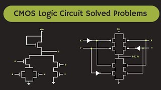
The CMOS XNOR gate, also known as the exclusive NOR gate, is a digital logic gate that outputs a high signal (1) only when the number of high inputs is even—specifically, when both inputs are the same. This behavior makes the XNOR operation useful for various applications, including parity checking and arithmetic functions. The truth table, outlined below, clearly represents the relationship between the two inputs (A and B) and the output (Vout).
Truth Table for CMOS XNOR Gate
- Inputs: A, B
- Output: Vout
| A | B | Vout |
|---|---|---|
| 0 | 0 | 1 |
| 0 | 1 | 0 |
| 1 | 0 | 0 |
| 1 | 1 | 1 |
The output is high (1) in two scenarios: when both inputs are 0 or when both inputs are 1. The significance of this gate lies in its ability to perform operations that require the detection of equality between two binary values.
Youtube Videos


Audio Book
Dive deep into the subject with an immersive audiobook experience.
Truth Table Overview
Chapter 1 of 1
🔒 Unlock Audio Chapter
Sign up and enroll to access the full audio experience
Chapter Content
| Input | Input | Output |
|---|---|---|
| 0 | 0 | 1 |
| 0 | 1 | 0 |
| 1 | 0 | 0 |
| 1 | 1 | 1 |
Detailed Explanation
The XNOR gate is a digital logic gate that outputs true or high (1) only when its inputs are the same. The truth table for the XNOR gate clearly shows four possible combinations of inputs:
- When both inputs (A and B) are 0, the output is 1, indicating they are equal.
- When one input is 0 and the other is 1, the output is 0, indicating they are not equal.
- Similarly, when one input is 1 and the other is 0, the output is again 0.
- Finally, when both inputs are 1, the output is again 1. This behavior reflects the logical equivalence of the inputs.
Examples & Analogies
Think of the XNOR gate as a matching game. Imagine you're sorting pairs of socks. If both socks are of the same color, you keep them together (output is 1). However, if you have one red sock and one blue sock, you set them apart (output is 0). The XNOR gate works in a similar way, confirming a match (1) or a mismatch (0) between its inputs.
Key Concepts
-
XNOR Gate: Outputs high when inputs are the same.
-
Truth Table: Displays the relationship between inputs and outputs for logic gates.
-
Digital Circuit Application: Used in error detection and parity checking.
Examples & Applications
Example of XNOR output: For inputs 1 and 1, the output is 1.
In a parity checker, if both inputs are the same, no error is detected.
Memory Aids
Interactive tools to help you remember key concepts
Rhymes
For equal bits, the XNOR shines, outputs high, it's by design!
Stories
Once upon a time, two signals met at a gate. They wanted to know if they were the same. When they both were low or both were high, the gate cheered and shouted '1!' But when one was low and the other was high, it whispered '0', signaling the difference.
Memory Tools
Remember: XNOR is for 'Xact' matches, it only says yes when the inputs are the same.
Acronyms
XNOR
'Xactly Same Not Output Reversed.'
Flash Cards
Glossary
- CMOS
Complementary Metal-Oxide-Semiconductor, a technology for constructing integrated circuits.
- XNOR Gate
A logic gate that outputs true or 1 only when the inputs are the same.
- Truth Table
A table that describes the output of a logic gate based on all possible input combinations.
- Digital Circuit
An electronic circuit that operates on binary values.
Reference links
Supplementary resources to enhance your learning experience.