
CMOS XNOR Gate
Enroll to start learning
You’ve not yet enrolled in this course. Please enroll for free to listen to audio lessons, classroom podcasts and take practice test.
Interactive Audio Lesson
Listen to a student-teacher conversation explaining the topic in a relatable way.
Overview of the XNOR Gate
🔒 Unlock Audio Lesson
Sign up and enroll to listen to this audio lesson

Today, we'll be discussing the CMOS XNOR gate. Can anyone tell me what an XNOR gate does?

It gives a high output when both inputs are the same, right?
Exactly! That's a key property of the XNOR gate. It outputs a high signal when both inputs are either high or low. This is useful for parity checking. Now, what can you tell me about how it operates?

When both inputs are the same, the output is 1. If they are different, the output is 0.
Great! That's correct. Can anyone explain why this property is useful in digital circuits?

It helps in detecting errors and ensuring data integrity.
Perfect! Let's look at the truth table for the XNOR gate to reinforce these concepts.
Truth Table of the XNOR Gate
🔒 Unlock Audio Lesson
Sign up and enroll to listen to this audio lesson

Here's the truth table for the CMOS XNOR gate. Can someone help me fill out what the output would be if both inputs are 1?
The output would be 1 since both inputs are the same!
Correct! Now, what would happen if Input A is 0 and Input B is 1?

The output would be 0 because the inputs are different.
Excellent! So we can summarize that the output is only high when both inputs match. Why is it beneficial to use a gate like this in circuits?
It simplifies the circuit for operations like equality check and ensures reliability.
Exactly! Well done.
Significance and Applications of XNOR Gates
🔒 Unlock Audio Lesson
Sign up and enroll to listen to this audio lesson
Now that we know how the XNOR gate works, let's talk about its applications. Can anyone think of where we might use an XNOR gate?
In error detection circuits?
Correct! XNOR gates are perfect for error-checking algorithms. What about other uses?
They're used in parity generators and checkers.
That's right! Parity can help determine if data has been corrupted. By the way, do you remember how to identify the XNOR in a circuit?
Yeah! It's often denoted as a combination of XOR with a bubble on the output to indicate inversion.
Exactly! Great job, everyone.
Introduction & Overview
Read summaries of the section's main ideas at different levels of detail.
Quick Overview
Standard
This section discusses the CMOS XNOR gate, a fundamental digital logic gate that gives a high output when both inputs are either high or low. It explains how the XNOR gate functions, its truth table, and its significance in digital design, particularly in error detection and parity operations.
Detailed
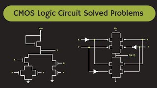
CMOS XNOR Gate
The CMOS XNOR gate is one of the essential digital logic gates that produces an output of high (1) when both of its inputs are the same, either both being high (1) or both low (0). This property makes the XNOR gate a useful tool in applications such as parity checking and error detection in digital circuits. The XNOR gate is essentially the complement of the XOR gate, which outputs high only when the inputs differ.
Operation of the XNOR Gate
The logic behind the XNOR gate is relatively straightforward:
- Output is High (1): When both inputs are the same; that is, both inputs are 0 or both are 1.
- Output is Low (0): When the inputs are different; that is, one input is 0 and the other is 1.
Truth Table
The following truth table summarizes the operation of the CMOS XNOR gate:
| Input A | Input B | Output (Vout) |
|---|---|---|
| 0 | 0 | 1 |
| 0 | 1 | 0 |
| 1 | 0 | 0 |
| 1 | 1 | 1 |
Significance in Digital Design
The CMOS XNOR gate enables straightforward implementations of equality checks and operates as a building block for more complex digital functions. Understanding its functionality helps in designing circuits that require logic operations for data integrity.
Youtube Videos


Audio Book
Dive deep into the subject with an immersive audiobook experience.
XNOR Gate Definition
Chapter 1 of 3
🔒 Unlock Audio Chapter
Sign up and enroll to access the full audio experience
Chapter Content
The CMOS XNOR gate is the complement of the XOR gate. It outputs a high value (1) when the inputs are the same (both high or both low).
Detailed Explanation
The XNOR gate, standing for 'exclusive NOR', is a digital logic gate that outputs true or high (1) when both of its inputs are the same. This can happen in two scenarios: both inputs are 0 (low) or both inputs are 1 (high). In contrast to the XOR gate, which outputs true when inputs are different, the XNOR gate gives a high output exclusively when inputs match.
Examples & Analogies
Imagine two friends deciding whether they both want to go to the same movie. If they both want to see the movie (both say 'yes' or agree), they go. If one wants to go and the other does not (one says 'yes' and the other says 'no'), they don't go. The XNOR gate behaves similarly: it only outputs a 'yes' when both inputs match.
XNOR Gate Operation
Chapter 2 of 3
🔒 Unlock Audio Chapter
Sign up and enroll to access the full audio experience
Chapter Content
● Operation:
○ The output is high (1) when both inputs are the same.
○ The output is low (0) when the inputs are different.
Detailed Explanation
The operation of the XNOR gate is straightforward. It produces a high output (1) when the two inputs A and B are identical. If both A and B are 0, the output is also 1. Similarly, if both A and B are 1, the output is again 1. Conversely, if A is 0 and B is 1, or A is 1 and B is 0, the output is low (0). This characteristic distinguishes it within logic circuits, especially where parity checks are necessary.
Examples & Analogies
Consider a light switch that only turns on when two conditions are met: both switches are in the 'up' position (on) or both are in the 'down' position (off). If one switch is up and the other is down, the light will not turn on. This is analogous to how the XNOR gate operates; the output lights up when both inputs match.
XNOR Gate Truth Table
Chapter 3 of 3
🔒 Unlock Audio Chapter
Sign up and enroll to access the full audio experience
Chapter Content
● XNOR Gate Truth Table
Input Input Output
(A) (B) (Vout)
0 0 1
0 1 0
1 0 0
1 1 1
Detailed Explanation
The truth table for the XNOR gate summarizes its behavior with all possible input combinations. It has four rows corresponding to the four potential input states:
1. When A is 0 and B is 0, the output is 1.
2. When A is 0 and B is 1, the output is 0.
3. When A is 1 and B is 0, the output is 0.
4. When A is 1 and B is 1, the output is 1. This table acts as a reference for predicting the behavior of the XNOR gate under any condition.
Examples & Analogies
Think of a light switch scenario where you want the light to turn on only when both conditions are met: both dimmers are set to the same level (either low or high). Reviewing these inputs through the truth table will help determine when the light will turn on or off, just as the XNOR truth table predicts the output based on input combinations.
Key Concepts
-
CMOS XNOR Gate: Outputs high (1) when both inputs are the same.
-
Truth Table: A representation of the output based on all possible input combinations.
-
Error Detection: Utilizing XNOR in systems for verifying data integrity.
Examples & Applications
In digital systems, an XNOR gate can be used to verify if two binary signals are the same, making it ideal for applications in error detection codes.
Parity bits implemented using XNOR gates can help in detecting single-bit errors in data transmission.
Memory Aids
Interactive tools to help you remember key concepts
Rhymes
If inputs match, the output's bright; XNOR shines when things are right.
Stories
Imagine two brothers who wear the same shirt; they high-five (output 1) when they're matched, but look away (output 0) when one wears blue while the other is red.
Memory Tools
Remember XNOR: Same = 1 (Like 'eXact' with inputs), Different = 0 (Not X-Nor).
Acronyms
XNOR
eXclusive Not OR - for equality check.
Flash Cards
Glossary
- CMOS
Complementary metal-oxide-semiconductor, a technology used for building integrated circuits.
- XNOR Gate
A digital logic gate that outputs true (1) when both of its inputs are the same.
- Truth Table
A table that shows all possible input values and their corresponding output values for a logic gate.
- Parity Checking
A method used in digital communication to detect errors in transmitted data.
Reference links
Supplementary resources to enhance your learning experience.