
CMOS XOR and XNOR Gates
Enroll to start learning
You’ve not yet enrolled in this course. Please enroll for free to listen to audio lessons, classroom podcasts and take practice test.
Interactive Audio Lesson
Listen to a student-teacher conversation explaining the topic in a relatable way.
Introduction to XOR and XNOR Gates
🔒 Unlock Audio Lesson
Sign up and enroll to listen to this audio lesson

Today, we are going to learn about the CMOS XOR and XNOR gates. Can anyone tell me what the XOR gate does?

It outputs high when the inputs are different, right?
Excellent! That's right. The XOR output is high when there is an odd number of 1s in the input. What about the XNOR gate?

The XNOR gate is the opposite; it outputs high when both inputs are the same.
Correct! So remember, 'XOR is odd, XNOR is even.' This will help you recall their operations.
CMOS Implementation of XOR Gate
🔒 Unlock Audio Lesson
Sign up and enroll to listen to this audio lesson

Now, let's discuss how to construct a CMOS XOR gate. Can anyone explain how we can achieve this?

We can combine NAND and NOR gates, right?
Exactly! We can derive XOR from these basic gates. Remember that the configuration needs both types of transistors to achieve the desired output.

So, it’s like creating a team where PMOS and NMOS work together!
Great analogy! They complement each other, just like all good teams do.
Truth Tables of XOR and XNOR Gates
🔒 Unlock Audio Lesson
Sign up and enroll to listen to this audio lesson
Let's examine the truth tables for both gates. How does the truth table for XOR look?
It has high output when the inputs differ: (0,0) gives 0, (0,1) gives 1, etc.
Right! And how is the XNOR truth table different?
It’s high only when both inputs are the same! (0,0) gives 1, and (1,1) gives 1.
Excellent job! Noticing these patterns is crucial for designing digital systems.
Applications of XOR and XNOR Gates
🔒 Unlock Audio Lesson
Sign up and enroll to listen to this audio lesson
Now, let’s talk about where we actually use these gates. Can anyone name an application?
I think they are used in error detection and correction.
Exactly! Parity checking circuits often use XOR gates for that purpose. Any other uses?
Are they also used in arithmetic operations, like adding two bits?
Absolutely! They are integral to many arithmetic logic units (ALUs). Great points!
Introduction & Overview
Read summaries of the section's main ideas at different levels of detail.
Quick Overview
Standard
In this section, we explore the CMOS XOR and XNOR gates, which are crucial for operations such as parity checking and error detection in digital circuits. We describe their construction, operational characteristics, and truth tables while understanding their significance in enhancing circuit functionality.
Detailed
Overview of CMOS XOR and XNOR Gates
The XOR (exclusive OR) and XNOR (exclusive NOR) gates are key components in digital logic systems, primarily for functions like parity checking, error detection, and basic arithmetic operations. These gates are slightly more complex than their NAND and NOR counterparts but remain grounded in complementary metal-oxide-semiconductor (CMOS) technology, where NMOS and PMOS transistors are used in tandem.
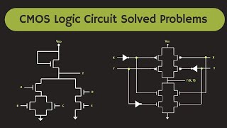
6.4.1 CMOS XOR Gate
The CMOS XOR gate produces a high output when the inputs are different, specifically when one input is high (1) and the other is low (0). It can be built by combining multiple NAND and NOR gates.
6.4.2 Truth Table for XOR Gate
| Input A | Input B | Output (Vout) |
|---|---|---|
| 0 | 0 | 0 |
| 0 | 1 | 1 |
| 1 | 0 | 1 |
| 1 | 1 | 0 |
6.4.3 CMOS XNOR Gate
Conversely, the XNOR gate outputs a high value when the inputs are the same (both high or both low). It represents the complement of the XOR function.
6.4.4 Truth Table for XNOR Gate
| Input A | Input B | Output (Vout) |
|---|---|---|
| 0 | 0 | 1 |
| 0 | 1 | 0 |
| 1 | 0 | 0 |
| 1 | 1 | 1 |
Both gates play critical roles in digital systems, enhancing computational capabilities and allowing complex operation implementations.
Youtube Videos


Audio Book
Dive deep into the subject with an immersive audiobook experience.
Introduction to XOR and XNOR Gates
Chapter 1 of 5
🔒 Unlock Audio Chapter
Sign up and enroll to access the full audio experience
Chapter Content
The XOR (exclusive OR) and XNOR (exclusive NOR) gates are essential in digital circuits for operations like parity checking, error detection, and arithmetic operations. These gates are more complex to implement than NAND and NOR gates, but they are still based on complementary transistor configurations.
Detailed Explanation
XOR and XNOR gates are crucial for various digital applications. The XOR gate gives a true output only when the number of true inputs is odd, which makes it useful in operations such as parity checking—ensuring data integrity by checking if the number of ones in a binary number is odd or even. The XNOR gate, being the complement of XOR, outputs true (1) when all inputs are the same. This property is particularly useful in error detection, as it can confirm if two signals are identical.
Examples & Analogies
Think of a light switch in a room where there are two switches: if one switch is up and the other is down, the light is on (XOR behavior). If both are up or both are down, the light is off. An XNOR gate, in contrast, only turns the light on when both switches match (both up or both down). This analogy can help students visualize how XOR and XNOR gates function based on their inputs.
CMOS XOR Gate Operation
Chapter 2 of 5
🔒 Unlock Audio Chapter
Sign up and enroll to access the full audio experience
Chapter Content
The CMOS XOR gate can be constructed by combining several NAND and NOR gates. It produces a high output (1) when an odd number of inputs are high.
- Operation:
- The output is high (1) when the inputs are different (i.e., one input is high and the other is low).
- The output is low (0) when both inputs are the same (both high or both low).
Detailed Explanation
The construction of a CMOS XOR gate typically involves combining multiple NAND and NOR gates in a specific configuration to achieve the desired output logic. The key operational trait is its output; it will be high only when there is an odd number of high inputs compared to low inputs. For example, if one input is high (1) and the other is low (0), the output will be high (1). Conversely, if both inputs are the same, whether both high (1) or both low (0), the output will be low (0).
Examples & Analogies
Imagine you and a friend are playing a game where you shout 'yes' (high, 1) or 'no' (low, 0). You both win only if one of you shouts 'yes' while the other shouts 'no'. So, if you shout 'yes' and your friend shouts 'no', you both celebrate a win! However, if you both shout the same answer, either both 'yes' or both 'no', there's no win to celebrate—a typical behavior of an XOR gate.
CMOS XOR Gate Truth Table
Chapter 3 of 5
🔒 Unlock Audio Chapter
Sign up and enroll to access the full audio experience
Chapter Content
Truth Table of the CMOS XOR Gate
| Input A | Input B | Output Vout |
|---|---|---|
| 0 | 0 | 0 |
| 0 | 1 | 1 |
| 1 | 0 | 1 |
| 1 | 1 | 0 |
Detailed Explanation
The truth table for the XOR gate summarizes its output based on the two possible inputs, A and B. When both inputs are zero (0), the output is also zero (0). When one input is one (1) and the other is zero (0), the output becomes one (1). Finally, when both inputs are one (1), the output is again zero (0). This clearly demonstrates the XOR functionality of giving a high output only when exactly one of the inputs is high.
Examples & Analogies
Consider two friends trying to guess whether it will rain today. If one thinks it will rain (yes = 1) while the other thinks it won't (no = 0), they conclude it’s a strong chance of rain (output = 1). If they both agree it will rain or both agree it won't, they come to no strong conclusion (output = 0). This illustrates how the XOR truth table operates based on different input conditions.
CMOS XNOR Gate Operation
Chapter 4 of 5
🔒 Unlock Audio Chapter
Sign up and enroll to access the full audio experience
Chapter Content
The CMOS XNOR gate is the complement of the XOR gate. It outputs a high value (1) when the inputs are the same (both high or both low).
- Operation:
- The output is high (1) when both inputs are the same.
- The output is low (0) when the inputs are different.
Detailed Explanation
The XNOR gate works by checking the equality of its inputs. If both inputs are the same, either both high or both low, it will produce a high output (1). If the inputs differ, the output drops to low (0). This gate is commonly used in applications where checking for equality between two signals is crucial, such as in digital comparison operations.
Examples & Analogies
Returning to the previous game scenario, if both friends shout the same answer—both say 'yes' or both say 'no'—they consider their guess valid and that indicates they agree (output = 1). If their answers differ, they can't agree on the forecast and thus their outcome is a disagreement (output = 0). This XNOR behavior emphasizes consensus, making it easier to understand and remember.
CMOS XNOR Gate Truth Table
Chapter 5 of 5
🔒 Unlock Audio Chapter
Sign up and enroll to access the full audio experience
Chapter Content
Truth Table of the CMOS XNOR Gate
| Input A | Input B | Output Vout |
|---|---|---|
| 0 | 0 | 1 |
| 0 | 1 | 0 |
| 1 | 0 | 0 |
| 1 | 1 | 1 |
Detailed Explanation
The truth table for the XNOR gate reflects its equality-checking functionality. When both A and B are zero, the output is one, meaning they are equal. When A is zero and B is one (or vice versa), the output drops to zero, indicating they are unequal. If both inputs are one, the output returns to one. This table illustrates the complements to the XOR function—where output reflects whether inputs match.
Examples & Analogies
Think of two siblings comparing their grades. If both siblings score the same grade—be it a low score or a perfect score—they celebrate their similarity (output = 1). However, if one scores high and the other low, they don't get the same satisfaction (output = 0). Thus, the XNOR gate mirrors their collective performance based on agreement!
Key Concepts
-
XOR Gate: Outputs a high signal when the inputs are different.
-
XNOR Gate: Outputs a high signal when the inputs are the same.
-
CMOS Technology: Involves NMOS and PMOS transistors configured complementarily.
-
Truth Table: A method to summarize the output of logic gates based on input combinations.
Examples & Applications
If the inputs for an XOR gate are (1, 0), the output will be 1, indicating an odd number of highs.
In an XNOR gate, if the inputs are (0, 0), the output is 1, showing both inputs are equal.
Memory Aids
Interactive tools to help you remember key concepts
Rhymes
XOR is for odd, XNOR for even, if they match, the output is heaven!
Stories
Imagine two friends deciding on lunch: if one wants pizza (1) and the other wants salad (0), they choose pizza (high). But if both want the same, like pizza (1,1), they say no to lunch (low).
Memory Tools
XNOR means match to catch; if both agree, it’s high, you see!
Acronyms
For XOR, think OFA
Outputs when First (or) Alternate is true.
Flash Cards
Glossary
- XOR Gate
A digital logic gate that outputs high when an odd number of its inputs are high.
- XNOR Gate
A digital logic gate that outputs high when an even number of its inputs are high.
- Truth Table
A table that illustrates the output values of a logic gate based on all possible input combinations.
- CMOS
Complementary Metal-Oxide-Semiconductor, a technology for constructing integrated circuits.
- Parity Checking
A method for detecting errors in binary data by checking for even or odd parity.
Reference links
Supplementary resources to enhance your learning experience.