
CMOS NOR Gate
Enroll to start learning
You’ve not yet enrolled in this course. Please enroll for free to listen to audio lessons, classroom podcasts and take practice test.
Interactive Audio Lesson
Listen to a student-teacher conversation explaining the topic in a relatable way.
Introduction to CMOS NOR Gate
🔒 Unlock Audio Lesson
Sign up and enroll to listen to this audio lesson

Today, we are going to learn about the CMOS NOR gate. Can anyone tell me what a NOR gate is?

Isn't it a gate that outputs a low signal when any input is high?
That's correct! However, it outputs high only when all inputs are low. Let's remember this with the phrase 'None Are High.' What are the configurations of PMOS and NMOS in a CMOS NOR gate?

I think it has PMOS transistors in series and NMOS in parallel.
Exactly! That's how it gets its unique function. Can anyone explain what happens during operation?

If both inputs are low, the PMOS turn on and the output is high.
Correct, and what happens when any input is high?

The NMOS turn on, pulling the output to low.
Great job everyone! To summarize, a CMOS NOR gate is designed with PMOS transistors in series and NMOS in parallel, outputting high only when inputs are low.
Truth Table of CMOS NOR Gate
🔒 Unlock Audio Lesson
Sign up and enroll to listen to this audio lesson

Now, let's take a look at the truth table for the CMOS NOR gate. Can someone read the first row out loud?
When A and B are both 0, the output is 1.
Excellent! And what do we have when A is 0 and B is 1?
The output is 0.
Correct! You see how the truth table clearly defines the NOR gate's operation? What's the advantage of using a CMOS NOR gate?
It uses less power because only one type of transistor is conducting at any given time.
Exactly! This low-power advantage makes CMOS technology very attractive for modern digital circuits.
Applications and Significance
🔒 Unlock Audio Lesson
Sign up and enroll to listen to this audio lesson
Who can think of an application where a CMOS NOR gate might be used?
In designing circuits that perform logical operations!
That's correct! In fact, NOR gates are universal: they can be combined to create any logical function. Isn’t that neat?
Yes! So, we could use NOR gates to create AND or OR gates too, right?
Absolutely! They serve as foundational components for complex circuits. This highlights the importance of understanding their operation.
Introduction & Overview
Read summaries of the section's main ideas at different levels of detail.
Quick Overview
Standard
The CMOS NOR gate consists of two PMOS transistors in series and two NMOS transistors in parallel. It outputs a low signal when either or both inputs are high and outputs a high signal only when both inputs are low, highlighting its role as a universal logic gate.
Detailed
CMOS NOR Gate
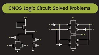
The CMOS NOR gate is one of the critical digital logic gates constructed using CMOS (Complementary Metal-Oxide-Semiconductor) technology. The gate architecture consists of the following:
- Transistor Configuration: This gate integrates two PMOS transistors in series and two NMOS transistors in parallel. The unique arrangement effectively determines the output based on the combination of input signals.
Operation
The NOR gate operates based on the following principles:
- Output High (1): When both input signals are low (0), the PMOS transistors are activated, allowing the output to reach high (1), while NMOS transistors remain off.
- Output Low (0): When either one or both of the input signals are high (1), the NMOS transistors conduct, pulling the output down to low (0).
Truth Table
The operation of the CMOS NOR gate can be summarized as follows:
| Input A | Input B | Output (Vout) |
|---|---|---|
| 0 | 0 | 1 |
| 0 | 1 | 0 |
| 1 | 0 | 0 |
| 1 | 1 | 0 |
The versatility of the CMOS NOR gate stems from its capability to perform any logical operation when configured suitably, designating it a universal gate within digital circuits.
Youtube Videos


Audio Book
Dive deep into the subject with an immersive audiobook experience.
CMOS NOR Gate Structure
Chapter 1 of 3
🔒 Unlock Audio Chapter
Sign up and enroll to access the full audio experience
Chapter Content
The CMOS NOR gate is made by connecting two NMOS transistors in parallel and two PMOS transistors in series. The NMOS transistors pull the output to ground when either of the inputs is high, while the PMOS transistors pull the output to Vdd only when both inputs are low.
Detailed Explanation
A CMOS NOR gate is designed using a unique configuration of NMOS and PMOS transistors. In this gate, two NMOS transistors are set up in parallel, and two PMOS transistors are arranged in series. This configuration dictates the behavior of the gate based on the input signals: the NMOS transistors will conduct (allow current to flow) when at least one input is high, which pulls the output to ground (low voltage). In contrast, both PMOS transistors will only conduct when both inputs are low, allowing the output to be pulled up to the supply voltage (Vdd). This interplay ensures that the output state reflects a logical NOR operation.
Examples & Analogies
Think of the CMOS NOR gate as a door system for a room. The NMOS transistors act like two guards at the door who prevent anyone from coming in (grounding the output) if even one person (input) is attempting to enter the room. In contrast, the PMOS transistors are like a strong gatekeeper who only unlocks the room (pulling the output up to Vdd) when no one is at the door (both inputs are low).
CMOS NOR Gate Operation
Chapter 2 of 3
🔒 Unlock Audio Chapter
Sign up and enroll to access the full audio experience
Chapter Content
● Operation:
○ When both inputs are low (0), both PMOS transistors turn on, pulling the output to high (1). Both NMOS transistors are off.
○ When either or both inputs are high (1), the output will be low (0) due to the conducting NMOS transistors.
Detailed Explanation
The operation of the CMOS NOR gate can be broken down into two key scenarios based on the input values. First, when both inputs are low (0), the condition allows both PMOS transistors to be activated, which results in the output being driven to a high state (1). In this case, the NMOS transistors do not conduct, keeping them off. Conversely, when either input is high (1), at least one NMOS transistor will conduct, forcing the output to a low state (0). This defines the logical function of the NOR gate, where the output is only high when all inputs are low.
Examples & Analogies
Consider a light switch system controlled by two switches (inputs). The light (output) only turns on when both switches are off (both inputs are low). If either switch is flipped on (either input is high), the light turns off. This is similar to how the CMOS NOR gate works, where it only allows a high output when there are no inputs signifying 'on' status.
CMOS NOR Gate Truth Table
Chapter 3 of 3
🔒 Unlock Audio Chapter
Sign up and enroll to access the full audio experience
Chapter Content
6.3.4 CMOS NOR Gate Truth Table
Input Input Output
AA BB VoutV_{out}
0 0 1
0 1 0
1 0 0
1 1 0
Detailed Explanation
The truth table for the CMOS NOR gate succinctly illustrates its behavior across all possible input combinations. It shows that when both inputs A and B are low (0), the output is high (1). In all other scenarios where at least one input is high (1), the output is low (0). This defines a NOR operation, where the result is true (1) only when all inputs are false (0). The truth table is an essential tool for understanding how the gate functions logically.
Examples & Analogies
Think of a family dinner where the dinner is only served when no one is late (both inputs A and B are low). If anyone arrives late (either input is high), dinner is not served (output is low). The truth table reflects these scenarios clearly, just like how everyone knows dinner is only ready when everyone's on time.
Key Concepts
-
CMOS NOR Gate: A gate that outputs high only when both inputs are low, consisting of PMOS in series and NMOS in parallel.
-
Truth Table: A table that outlines the output for every possible combination of input values.
Examples & Applications
In digital electronics, a CMOS NOR gate can be used in logic circuits to perform various functions, such as creating the equivalent of AND gates or OR gates through combinations.
Experimentally, if we connect two switches representing inputs A and B to a CMOS NOR gate, the connected output lights up only when both switches are off.
Memory Aids
Interactive tools to help you remember key concepts
Rhymes
When inputs are low, the output's high, in a NOR gate, that's no lie.
Stories
Imagine a kingdom where both gates are shut; only then will the castle's flag go up, which symbolizes high output.
Memory Tools
For a NOR gate to shine bright, both inputs must be at zero height.
Acronyms
Remember 'N' in NOR as No Outputs Raised, when any are
that's the keyphrase.
Flash Cards
Glossary
- CMOS
Complementary Metal-Oxide-Semiconductor, a technology for constructing integrated circuits.
- NOR Gate
A logic gate that outputs high only when all inputs are low.
- PMOS Transistor
A type of transistor that conducts when its gate voltage is low.
- NMOS Transistor
A type of transistor that conducts when its gate voltage is high.
Reference links
Supplementary resources to enhance your learning experience.