
Component Description
Interactive Audio Lesson
Listen to a student-teacher conversation explaining the topic in a relatable way.
Fin Component Characteristics
🔒 Unlock Audio Lesson
Sign up and enroll to listen to this audio lesson

Today we'll explore the vital components that make up a FinFET. Can anyone tell me what a FinFET is?

It's a type of transistor that has a fin shape!
Exactly! The fin itself is a narrow strip of silicon that forms the channel. This structure allows for better control compared to traditional MOSFETs. Student_2, do you know what surrounds this fin?

Is it the gate?
Correct! The gate is conductive and wraps around the fin. This multi-gate structure helps improve electrostatic control significantly. Let's remember this: 'More gates, less leakage.'

What about the source and drain? Where do they fit in?
Great question! The source and drain are heavily doped regions on either side of the fin, crucial for the transistor's function. They allow for effective charge injection and extraction.

And what does STI mean?
STI stands for Shallow Trench Isolation. It helps prevent transistors from interfering with each other. Remember, isolation improves reliability in circuits!
To recap, we discussed the fin, gate, source/drain regions, and STI. These components work in harmony to enhance the performance of FinFETs!
Types of FinFETs
🔒 Unlock Audio Lesson
Sign up and enroll to listen to this audio lesson

Now that we know about the components, let's discuss the types of FinFETs. Can anyone name one type?
There's the double-gate FinFET!
Exactly! The double-gate FinFET has a gate wrapping around two vertical sides. What do you think is the advantage of having a tri-gate FinFET, Student_2?
Maybe it has better control than the double-gate one?
Spot on! The tri-gate FinFET wraps around three sides, which maximizes the gate's electrostatic control. Remember: 'Tri-gate for triple control!'
What about the multi-fin FinFET?
Great point! The multi-fin FinFET connects several fins in parallel. This increases the current handling capability. 'More fins, more current!' Remember this for your exams!
So, each type is for different applications based on how much current we need?
Exactly! Each configuration offers unique benefits. To summarize, we talked about double-gate, tri-gate, and multi-fin FinFETs, and how their designs impact functionality.
Introduction & Overview
Read summaries of the section's main ideas at different levels of detail.
Quick Overview
Standard
The Component Description section details the various elements that constitute a FinFET, including the fin, gate, and source/drain regions. It presents different types of FinFETs and their defining characteristics, crucial for understanding their operation in modern semiconductor technology.
Detailed
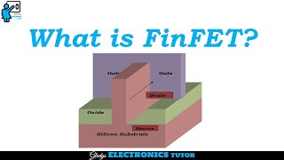
Component Description
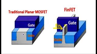
The FinFET (Fin Field Effect Transistor) comprises several crucial components that enhance its function and efficiency compared to traditional planar MOSFETs. Key components include:
- Fin: A narrow strip of silicon serving as the channel where charge carriers flow.
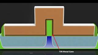
- Gate: This conductive material encases the fin on two or three sides, providing better electrostatic control over the channel.
- Gate Dielectric: A thin insulating layer (often made from high-κ materials) situated between the fin and the gate, reducing leakage current.
- Source/Drain: Heavily doped regions located on either side of the fin, allowing for efficient charge injection and extraction.
- Shallow Trench Isolation (STI): This structure isolates transistors from each other to prevent short-circuiting and cross-talk.
Types of FinFETs:
- Double-gate FinFET: The gate wraps around two vertical sides of the fin.
- Tri-gate FinFET: The gate encircles three sides (top and two sides), maximizing control.
- Multi-fin FinFET: This configuration connects multiple fins in parallel to increase current handling capacity.
Overall, these components and designs are pivotal in enhancing FinFET performance, particularly in deep sub-micron technology nodes.
Youtube Videos

Audio Book
Dive deep into the subject with an immersive audiobook experience.
Fin
Chapter 1 of 6
🔒 Unlock Audio Chapter
Sign up and enroll to access the full audio experience
Chapter Content
Narrow strip of silicon forming the channel.
Detailed Explanation
The fin is a crucial part of the FinFET structure, serving as the channel through which current flows. It is designed as a thin vertical strip of silicon. The narrow dimensions of the fin help in achieving better electrostatic control over the channel, which is essential for the FinFET's operation at reduced dimensions while minimizing leakage currents.
Examples & Analogies
Think of the fin as a narrow water pipe. Just as a narrower pipe allows for more precise control of water flow, the fin allows for better control of electrical current, enhancing the transistor's performance.
Gate
Chapter 2 of 6
🔒 Unlock Audio Chapter
Sign up and enroll to access the full audio experience
Chapter Content
Conductive material that surrounds the fin on 2 or 3 sides.
Detailed Explanation
The gate in a FinFET device is the conductive part that controls the flow of current through the fin. Unlike traditional transistors, the gate in FinFETs wraps around the fin on two or three sides, providing stronger control of the channel. This multi-gate geometry results in reduced off-state leakage and improved electrical characteristics of the device.
Examples & Analogies
Imagine a barbecue grill with multiple sides around a central barbecue area. Just as you would use the sides to control the heat distribution better, the gate around the fin controls the electrical field, which regulates the current flow more effectively.
Gate Dielectric
Chapter 3 of 6
🔒 Unlock Audio Chapter
Sign up and enroll to access the full audio experience
Chapter Content
Thin insulating layer between gate and fin (often high-κ).
Detailed Explanation
The gate dielectric is a crucial insulating layer placed between the gate and the fin to prevent current from flowing directly between these two components when it is not needed. This layer is typically made from high-k (high dielectric constant) materials, which allow for thinner layers to be used while maintaining the required insulating properties, thus contributing to the overall performance by reducing leakage currents.
Examples & Analogies
Think of the gate dielectric like a plastic wrap on food. It keeps the food fresh and contained, just like the dielectric keeps the electrical signals contained within the FinFET, preventing unwanted leakage.
Source/Drain
Chapter 4 of 6
🔒 Unlock Audio Chapter
Sign up and enroll to access the full audio experience
Chapter Content
Heavily doped regions on either side of the fin.
Detailed Explanation
The source and drain are heavily doped regions located on either side of the fin. Their primary purpose is to inject and withdraw carriers (electrons or holes) from the channel when the transistor is active. The doping level is significant, which ensures that these regions can quickly supply or accept charge carriers, thus enhancing the performance of the FinFET.
Examples & Analogies
You can think of the source and drain like the inlet and outlet of a fountain. The water (or current) comes from the source and flows out through the drain, with the fountain fin representing the water's path. The ease of flow at the inlet and outlet is crucial for the fountain to operate smoothly.
Shallow Trench Isolation (STI)
Chapter 5 of 6
🔒 Unlock Audio Chapter
Sign up and enroll to access the full audio experience
Chapter Content
Used to isolate transistors from each other.
Detailed Explanation
Shallow Trench Isolation (STI) is a technique used to prevent electrical interference between adjacent FinFET devices. By creating trenches filled with an insulating material around the fins, STI effectively isolates them, reducing the chances of crosstalk and ensuring that each transistor operates independently without affecting others.
Examples & Analogies
Consider STI like the fencing between yards in a neighborhood. Just as fences keep neighbors' properties separate to prevent mixing and interference, STI keeps the electrical activities of different FinFETs distinct, ensuring optimal performance.
Types of FinFETs
Chapter 6 of 6
🔒 Unlock Audio Chapter
Sign up and enroll to access the full audio experience
Chapter Content
● Double-gate FinFET: Gate on two vertical sides. ● Tri-gate FinFET: Gate wraps around three sides (top + sides). ● Multi-fin FinFET: Multiple fins connected in parallel for increased current handling.
Detailed Explanation
FinFETs come in various configurations: Double-gate FinFETs have gates on two sides, while Tri-gate FinFETs envelop the fin on three sides, providing enhanced control. Multi-fin FinFETs utilize multiple fins that are connected in parallel to improve current handling capacity, making them effective for higher performance applications.
Examples & Analogies
Think of the different types of FinFETs like different styles of umbrellas. A double-gate umbrella covers two sides, a tri-gate umbrella offers more coverage, while a multi-fin umbrella has several canopies for maximum protection from the rain. Each style serves a different purpose based on the need for coverage and support.
Key Concepts
-
Fin: The channel of the FinFET.
-
Gate: The electrostatic control element surrounding the fin.
-
Gate Dielectric: Insulating layer that reduces leakage.
-
Source/Drain: Charge input and output conduits.
-
STI: Prevents interference between transistors.
-
Double-gate FinFET: A configuration with gates on two sides.
-
Tri-gate FinFET: Gate surrounds three sides for enhanced control.
-
Multi-fin FinFET: Combines multiple fins for increased capacity.
Examples & Applications
The Fin, acting as the channel, ensures effective control in a tri-gate FinFET by wrapping around the top and sides, allowing better performance.
In multi-fin FinFETs, several fins increase the current capacity, demonstrating the advantage of scaling in performance.
Memory Aids
Interactive tools to help you remember key concepts
Rhymes
Fins are thin, where currents swim; gates wrap tight, keeping it right.
Stories
Once in a circuit board, a fin stood tall and narrow, surrounded by gates which kept electricity flowing just like a well-guarded river.
Memory Tools
F5: Fin, Fin Height, Fin Width; remember these key parameters of a FinFET!
Acronyms
GFS
Gate
Fin
Source - the three essentials of FinFET design.
Flash Cards
Glossary
- Fin
A narrow strip of silicon that forms the channel in a FinFET.
- Gate
A conductive material that surrounds the fin and controls the channel.
- Gate Dielectric
An insulating layer between the gate and fin, commonly high-κ.
- Source/Drain
Heavily doped regions on either side of the fin for charge injection and extraction.
- Shallow Trench Isolation (STI)
A method to isolate transistors to prevent interference.
- Doublegate FinFET
A FinFET type with gates on two vertical sides of the fin.
- Trigate FinFET
A FinFET type with gates wrapping around three sides of the fin.
- Multifin FinFET
A configuration of multiple fins connected in parallel for higher current handling.
Reference links
Supplementary resources to enhance your learning experience.